
hydraulic check valve
A one-way valve and hydraulic technology, applied in the field of hydraulic one-way valve, can solve the problems of valve core moving vibration, unable to reset seal, and noise generation, and achieve the effects of ensuring stability, fast flow speed, and reducing vibration and noise
Patent Information
- Authority / Receiving Office
- CN · China
- Patent Type
- Patents(China)
- Current Assignee / Owner
- Publication Date
- 2017-02-15
Smart Images
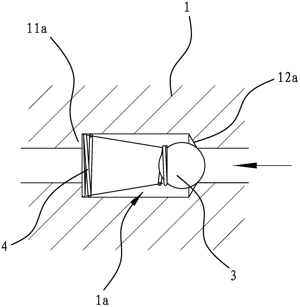
Figure 1 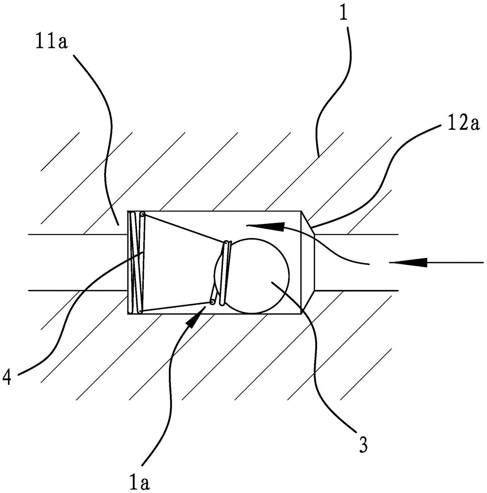
Figure 2 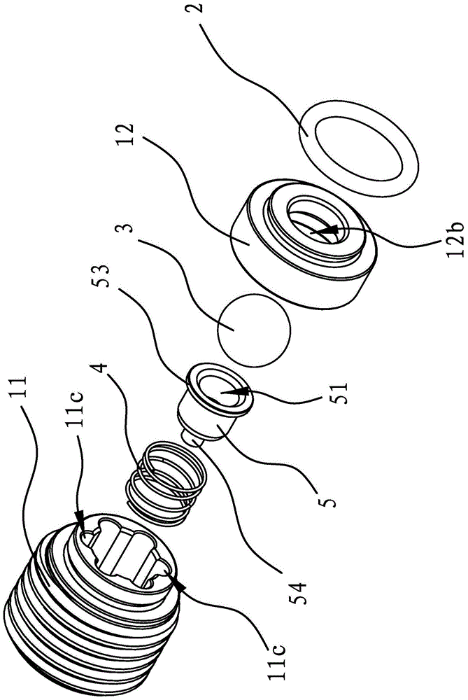
Figure 3
Abstract
Description
technical field
[0001] The invention belongs to the technical field of valves, and relates to a valve, in particular to a hydraulic one-way valve. Background technique
[0002] A one-way valve is a valve in which the fluid flowing through the one-way valve can only flow from the inlet to the outlet, and the fluid at the outlet cannot flow back. Because of its anti-backflow characteristics, check valves are used in various hydraulic tools and hydraulic equipment.
[0003] Such as figure 1 As shown, the structure of the one-way valve generally includes a body with a cylindrical through hole inside, a valve core and a spring both arranged in the body, and the inner walls at both ends of the body have annular sealing surfaces and annular shoulders respectively. The spool is located between the sealing surface and the shoulder, and the spring is located between the spool and the shoulder and can exert force on the spool, so that the spool leans against the sealing surface to fo...
Examples
Embodiment 1
[0029] Such as image 3 and Figure 4 As shown, the hydraulic check valve is used at the oil outlet of the plunger pump, and includes a cylindrical body 1 with a through-hole 1a penetrating in the axial direction, a valve core 3 and a ball all arranged in the through-hole 1a. Holder 5 and spring 4, the inner wall of the front end of body 1 has an annular sealing surface 12a coaxial with body 1, and the inner wall of main body 1 rear end has an annular shoulder 11a coaxial with body 1. The spool 3 is located between the shoulder 11a and the sealing surface 12a, the spring 4 is arranged between the shoulder 11a and the spool 3 and the spool 3 can abut against the sealing surface 12a and form a seal under the elastic force of the spring 4, The ball holder 5 is arranged between the valve core 3 and the spring 4 .
[0030] In this embodiment, the valve core 3 is a bearing steel ball; the front part of the ball holder 5 has an opening 51 where the rear end of the valve core 3 can ...
Embodiment 2
[0037] The technical solution in this embodiment is substantially the same as that in Embodiment 1, except that the hydraulic check valve in this embodiment is used at the oil inlet of the plunger pump, and both the valve body 11 and the valve seat 12 are cylindrical , the rear end of the valve seat 12 is sleeved on the outside of the valve body 11 and the two are threaded, the rear end surface of the valve seat 12 is flat with the rear end surface of the valve body 11; the strip hole 6 is opened on the front end surface of the valve seat 12 , the annular groove is located on the rear end surface of the valve seat 12;
[0038] In the hydraulic check valve, the radial limit of the spool 3 and the flow passage for the liquid medium to flow through can be used in addition to the above-mentioned technical solutions of the through hole 11b as a round hole and the flow groove 11c, the following technologies can also be used Solution: such as Figure 8 and Figure 9 As shown, the s...