
Method for pinpointing target through multi-degree of freedom adjusting supporting device
A technology of support device and degrees of freedom, applied in the direction of control using feedback, can solve the problems of low adjustment accuracy, time-consuming and labor-intensive, etc., to achieve the effect of lifting and fine adjustment, and realizing precise adjustment of multiple degrees of freedom.
Patent Information
- Authority / Receiving Office
- CN · China
- Patent Type
- Applications(China)
- Current Assignee / Owner
- Publication Date
- 2014-09-03
- Estimated Expiration
- Not applicable · inactive patent
Smart Images
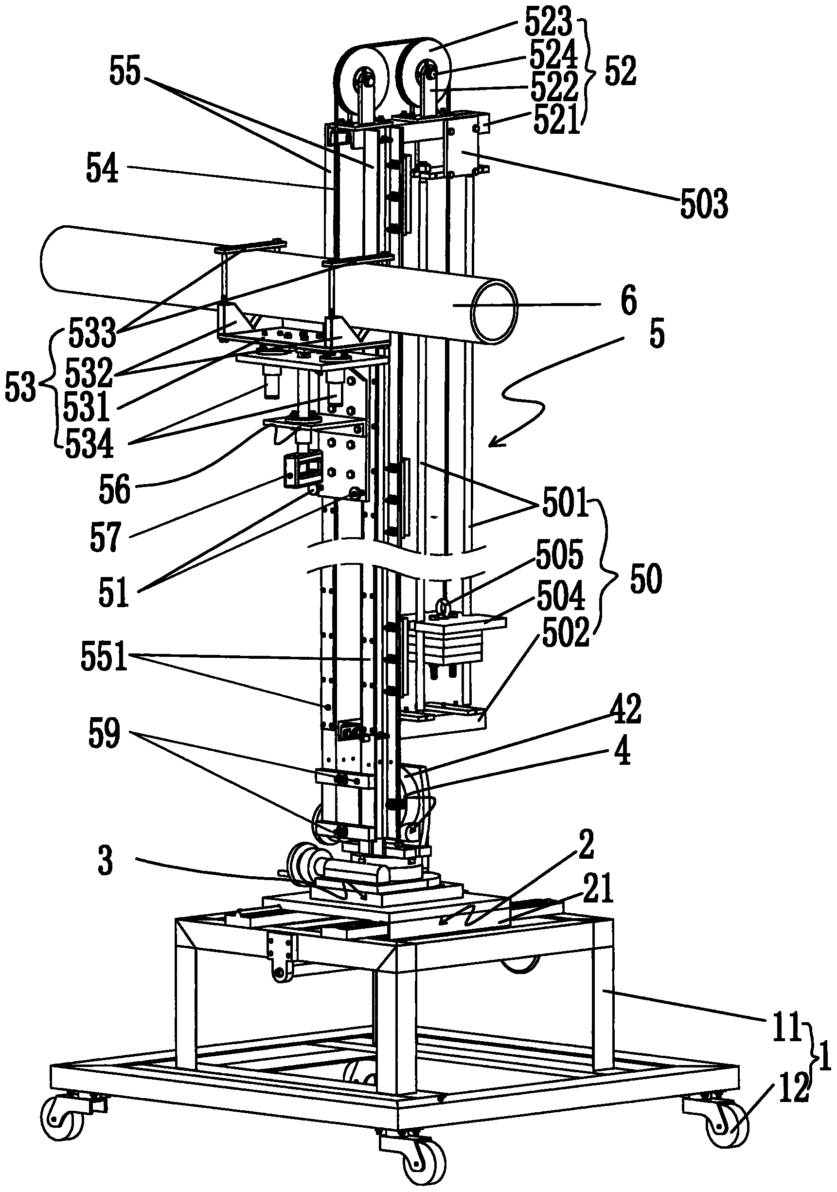
Figure 1 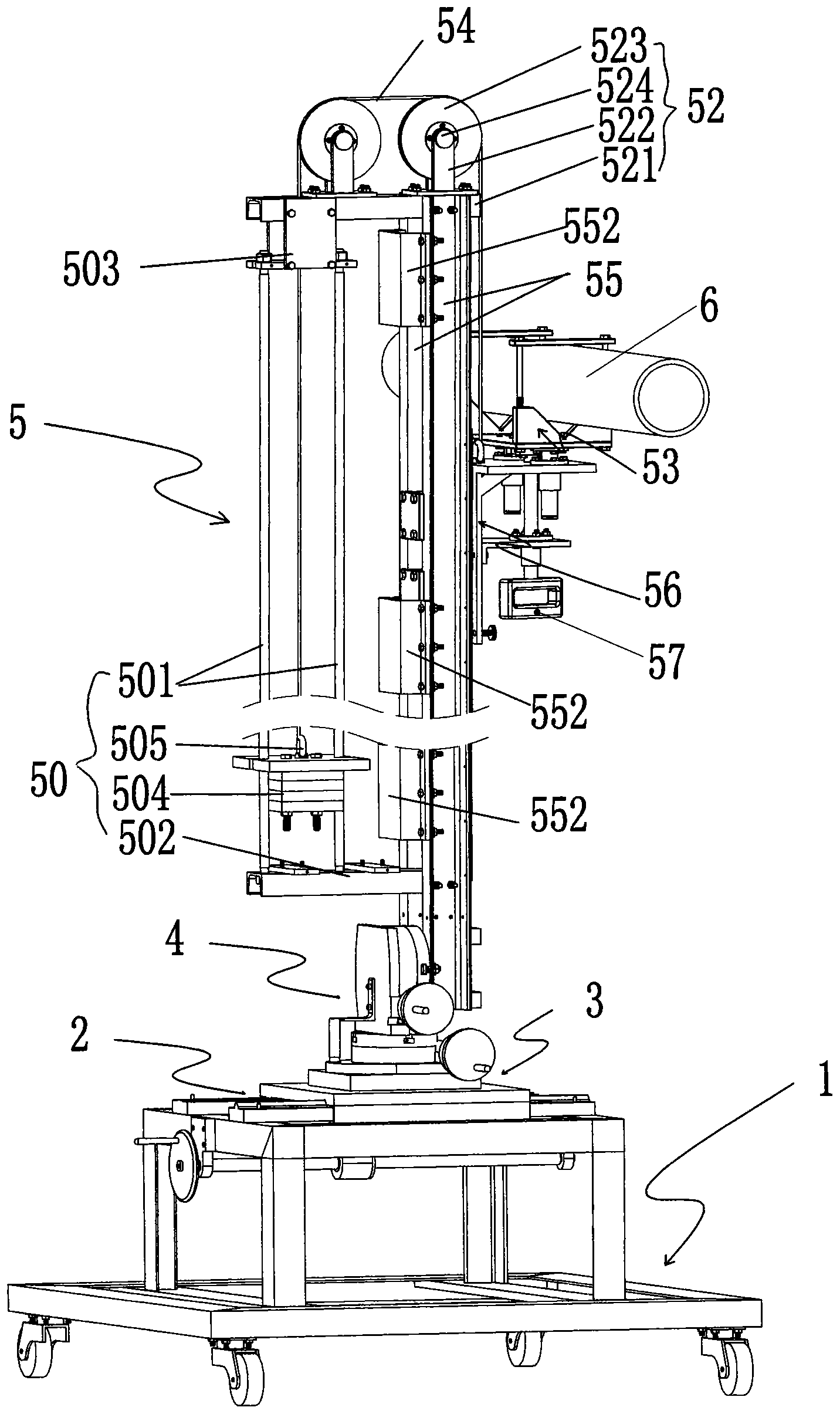
Figure 2 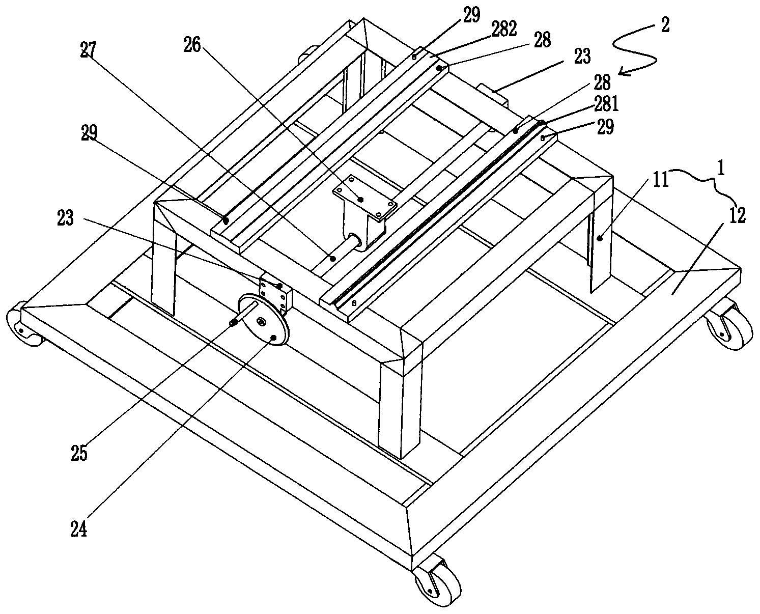
Figure 3
Abstract
Description
technical field
[0001] The invention belongs to a method for adjusting the position of a collimator, in particular to a method for realizing accurate alignment of a target by adjusting a supporting device with multiple degrees of freedom. Background technique
[0002] Collimated light pipes are widely used in optical experimental research, and collimated light pipes can emit parallel light. In the experiment, adjust the collimator so that the collimated light points to the target position. The position adjustment of the small collimator can be realized by the spacer, but for the adjustment of the large collimator, if it is carried manually and adjusted with the spacer, it will be time-consuming and laborious, and the adjustment accuracy is not high. Contents of the invention
[0003] The object of the present invention is to provide a method for realizing precise alignment of a target by adjusting a support device with multiple degrees of freedom, so as to realize multi-d...
Examples
Embodiment Construction
[0028] The present invention will be further described below in conjunction with accompanying drawings and examples.
[0029] Such as figure 1 , figure 2 , Figure 8 As shown, a multi-degree-of-freedom adjustment support device 9 for placing large and medium-sized collimators is convenient for carrying large and medium-sized collimators 6 and adjusting multiple degrees of freedom for large and medium-sized collimators 6, including a base 1, a horizontal sliding device 2, Horizontal rotary device 3, vertical rotary device 4, lifting device 5.
[0030] Such as image 3 , Figure 4 As shown, the base 1 includes a base bracket 11 and casters 12, and four casters 12 are installed at the bottom of the base bracket 11 to facilitate the movement of the entire device.
[0031] Such as image 3 , Figure 4 As shown, the described horizontal sliding device 2 includes a horizontal slide table 21, a first hand wheel 24, a first handle 25, a screw shaft seat 26, a lead screw 27, a l...