
Photoelectric detection method of powder spreading amount for rapid prototyping
A detection method and photoelectric technology, applied in the direction of weighing equipment, weighing and measuring devices of materials with special properties/forms, can solve the problems of incomplete powder spreading, difficult accurate measurement, and scrapping in the powder spreading area. The effect of improving forming accuracy and quality, simple method steps and high detection sensitivity
Patent Information
- Authority / Receiving Office
- CN · China
- Patent Type
- Patents(China)
- Current Assignee / Owner
- Publication Date
- 2017-03-29
Smart Images
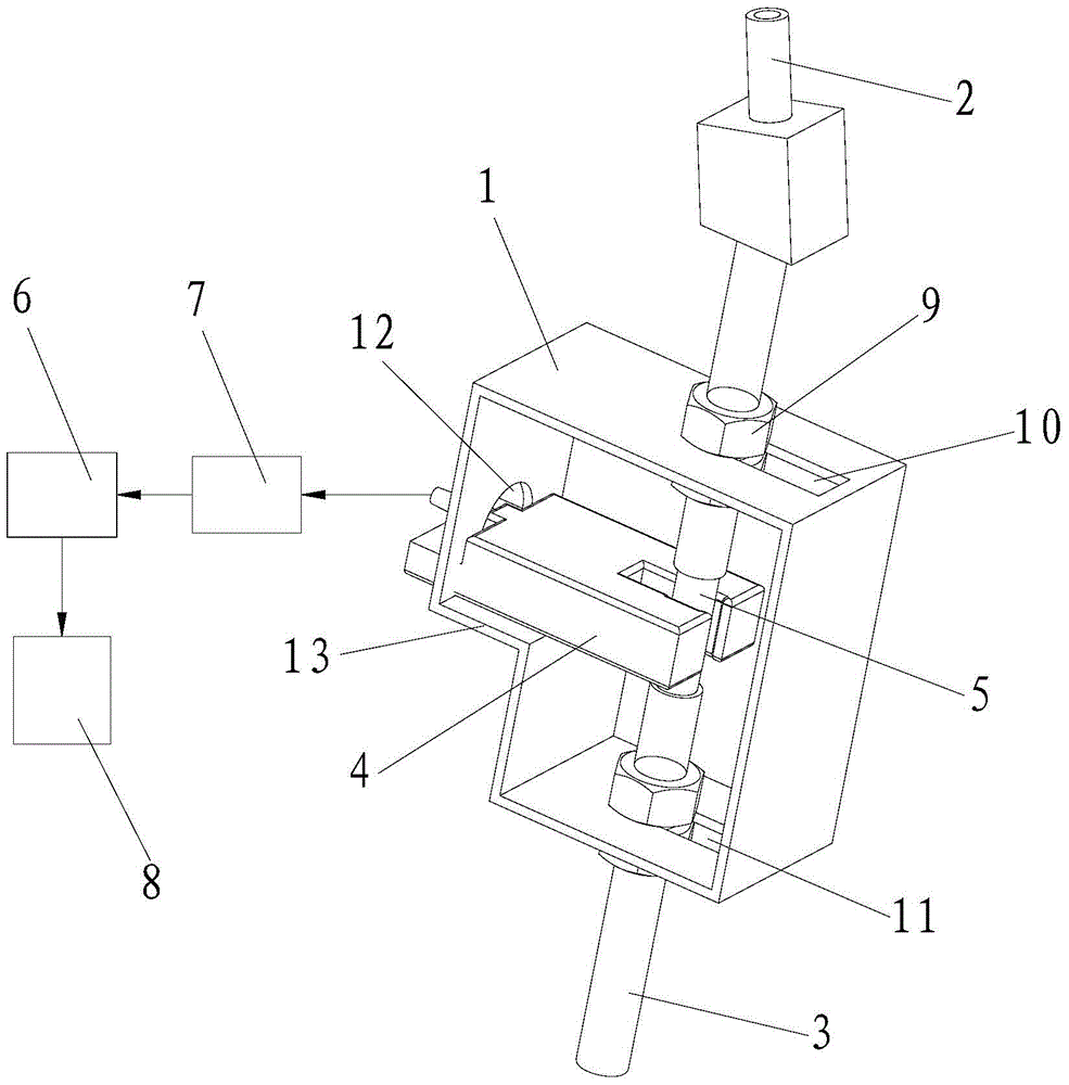
Figure 1 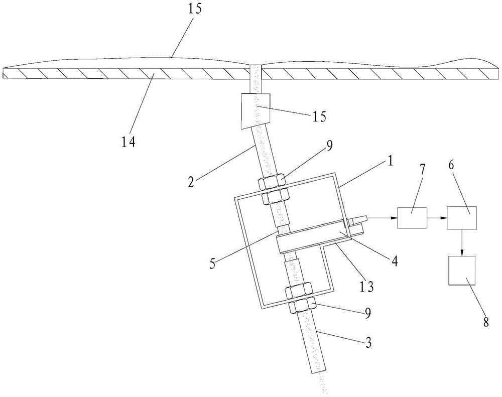
Figure 2
Abstract
Description
technical field
[0001] The invention belongs to the technical field of rapid prototyping, and in particular relates to a photoelectric detection method for powder spreading amount of rapid prototyping. Background technique
[0002] Automatic powder-spreading high-energy beam selective melting technology is a newly developed direct 3D printing technology for metal parts. Its principle is to use a computer to layer the 3D CAD model and process the cross-section information, and then input the cross-section data into the 3D printer. The data spreads the metal powder layer by layer and uses the high-energy beam to melt the selected area of the powder layer. After all the cross-sections are melted layer by layer and superimposed, the three-dimensional solid parts of the designed structural shape are obtained. The powder spreading process is a key process in the automatic powder spreading high-energy beam selective melting technology. The thickness and uniformity of the powder l...
Examples
Embodiment Construction
[0040] like figure 1 As shown, the rapid prototyping powder spreading amount photoelectric detection system of the present invention includes a powder flow detection mechanism, a controller 6 and a computer 8 connected to the controller 6, and the powder flow detection mechanism includes a fixed bracket 1 and a fixed connection On the fixed support 1, the upper and lower powder tube 2, the lower powder tube 3 and the photoelectric sensor 4, the light-transmitting tube 5 is connected between the upper and lower powder tube 2 and the lower powder tube 3, and the emission of the photoelectric sensor 4 The end and the receiving end are respectively located on both sides of the transparent tube 5, the input end of the controller 6 is connected with a timer 7, and the signal output end of the photoelectric sensor 4 is connected with the signal input end of the timer 7.
[0041] like figure 1 As shown, in this embodiment, the upper and lower powder pipes 2 and 3 are vertically and f...