
A display stand for valve display with detection function
A display stand and valve technology, applied in applications, display stands, home appliances, etc., can solve the problems of not being able to display valves well, and achieve the effects of improving publicity effects, convenient erection, and convenient use
Patent Information
- Authority / Receiving Office
- CN · China
- Patent Type
- Patents(China)
- Current Assignee / Owner
- Publication Date
- 2019-05-28
Smart Images
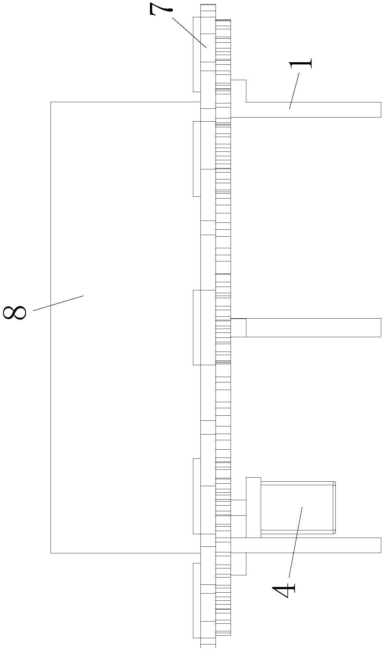
Figure 1 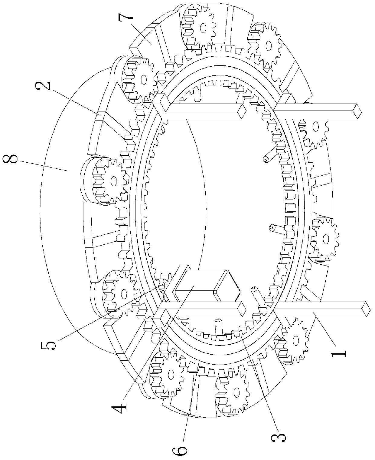
Figure 2 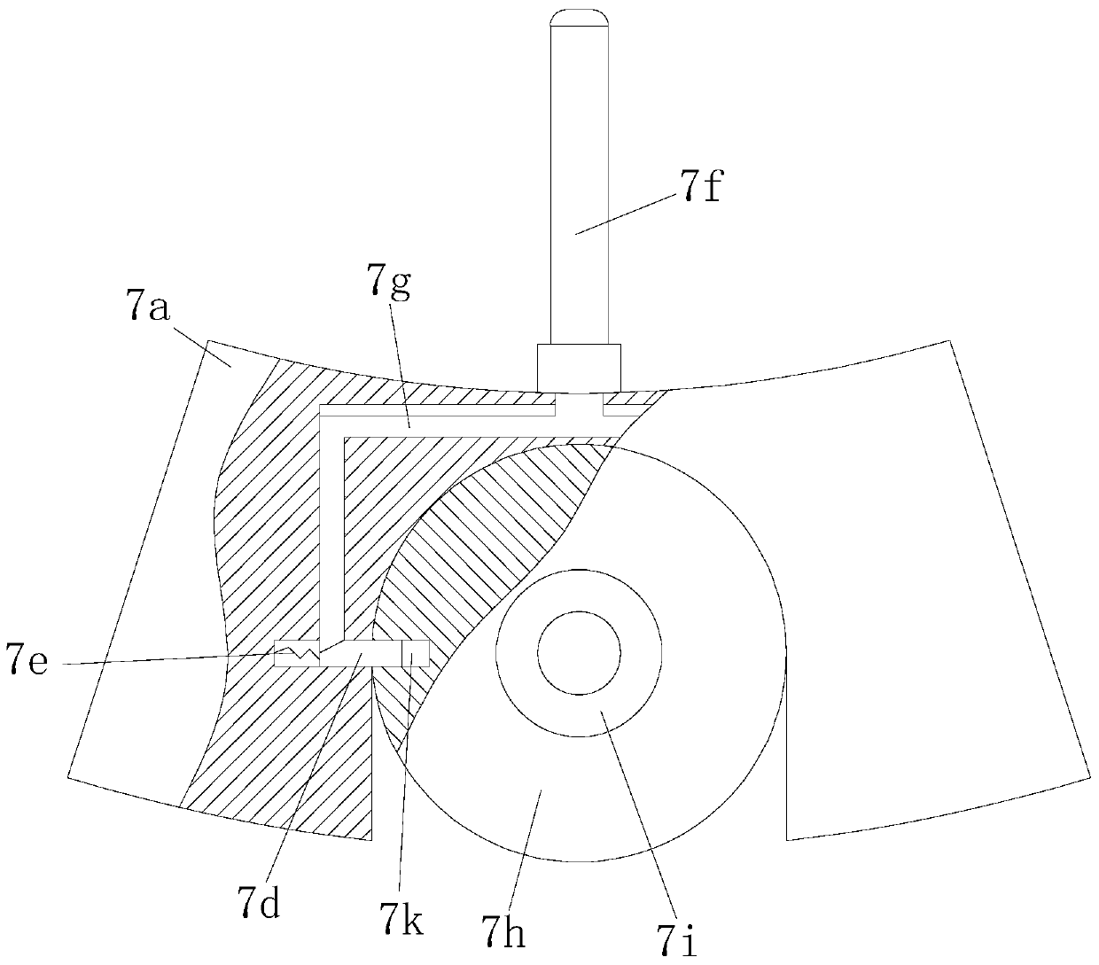
Figure 3
Abstract
Description
technical field
[0001] The invention relates to the technical field of valve display equipment, in particular to a display stand for valve display with a detection function. Background technique
[0002] With the development of the times, more and more valves are used, and the valve manufacturing industry has achieved unprecedented development. my country's valve manufacturing industry, after long-term development, has become more and more specialized, including ball valves, butterfly valves, regulating valves, pressure reducing valves, etc., with higher and higher technological content and fiercer competition. Therefore, every enterprise must improve its own production technology in order to be competitive in the market.
[0003] In the sales process of the existing valves, the valves are basically placed on ordinary shelves for people to visit, but the ordinary shelves cannot display the valves well. Therefore, the market needs a display stand that is easy to use and can...
Examples
Embodiment Construction
[0015] In order to make the purpose, technical solutions and beneficial effects of the present invention more clear, the preferred embodiments of the present invention will be described in detail below in conjunction with the accompanying drawings, and the present invention will be further described to facilitate the understanding of technical personnel.
[0016] Such as Figure 1 to Figure 4 As shown, a display stand for valve display with detection function includes a circular support frame 1, and a rotatable circular driven frame 2 is installed on the circular support frame 1, and the circular driven frame 2 A No. 1 ring gear 3 is fixed on the inner wall of the circular support frame 1. A motor 4 is installed on the bottom of the circular support frame 1. A driving gear 5 is installed on the shaft of the motor 4. The driving gear 5 is meshed with the No. 1 ring gear 3 , the outer wall of the circular support frame 1 is fixed with the second ring gear 6, the outer wall of th...