
High-power LED lamp integrated cooling shell
A heat dissipation shell and LED lamp technology, which is applied in lighting and heating equipment, semiconductor devices of light-emitting elements, cooling/heating devices of lighting devices, etc., can solve the problems of increased product weight, unfavorable wiring, and difficult molding, etc., to achieve Reduce product weight, avoid warping phenomenon, simple and beautiful appearance
Patent Information
- Authority / Receiving Office
- CN · China
- Patent Type
- Patents(China)
- Current Assignee / Owner
- Publication Date
- 2019-01-18
Smart Images
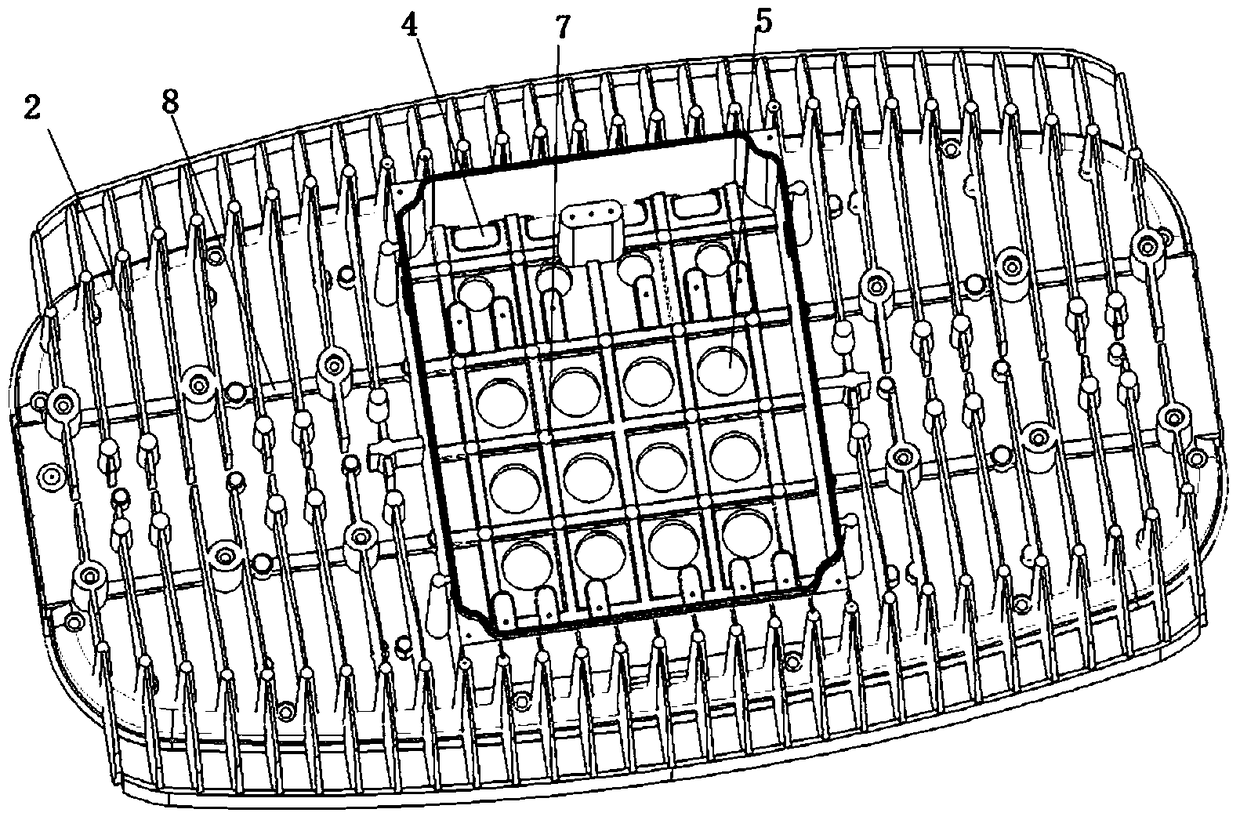
Figure 1 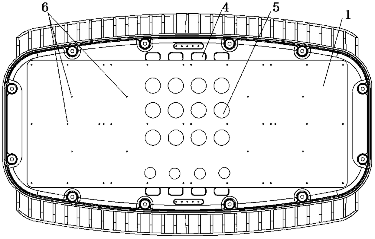
Figure 2 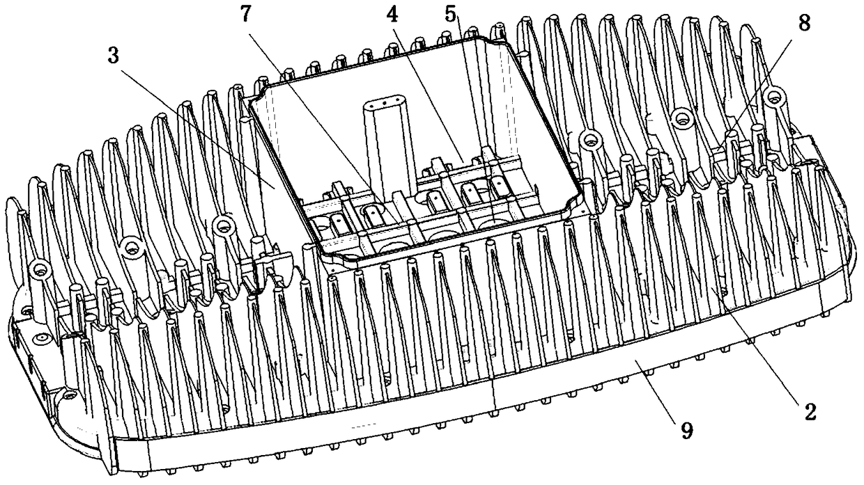
Figure 3
Abstract
Description
technical field
[0001] The invention relates to a heat dissipation shell of a high-power LED lamp. Background technique
[0002] With the popularity of high-power LED lamps, issues such as power supply reliability, applicability, and heat dissipation need to be comprehensively considered in design. At present, the back of the heat dissipation housing of common high-power LED lamps will be provided with multiple rows of heat dissipation fins, the front of the heat dissipation housing will be provided with a mounting structure, and one or more LED chip mounting substrates will be fixed on the front of the mounting structure ( A single headlight is usually a LED chip mounting substrate, which is located in the middle of the front; a double headlight is usually two LED chip mounting substrates, which are located on the two wings of the front), and a power supply compartment is recessed in other positions on the front (for a single headlight, usually adjacent to LED chip mountin...
Examples
Embodiment Construction
[0027] Such as Figure 1 to Figure 3 As shown, the high-power LED lamp has an integrated heat dissipation shell, and the back of the heat dissipation shell is provided with multiple rows of heat dissipation fins, and the heat dissipation fins are perpendicular to the length direction of the heat dissipation shell and parallel to the width direction of the heat dissipation shell; The front part is provided with a flat-plate mounting structure, and a plurality of reinforcing ribs are provided along the length direction on the back of the entire mounting structure (radiating fins are naturally used as reinforcing ribs in the width direction).
[0028] The power supply compartment and one or more LED chip mounting substrates are respectively fixed on the back and front of the mounting structure, and the projection positions of the power supply compartment and the LED chip mounting substrate on the mounting structure are staggered; correspondingly, on the back of the heat dissipatio...