
A musical lantern based on a carrying mechanism
A technology of musical lanterns and turntables, applied to components of lighting devices, lighting devices, electric light sources, etc., can solve the problems of high production cost, complex structure, and low decorative value, and achieve low cost, convenient production, and simple structure Effect
Patent Information
- Authority / Receiving Office
- CN · China
- Patent Type
- Patents(China)
- Current Assignee / Owner
- Publication Date
- 2018-08-21
- Estimated Expiration
- Not applicable · inactive patent
Smart Images
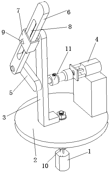
Figure 1
Abstract
Description
technical field
[0001] The invention belongs to the technical field of lighting and decoration, and in particular relates to a musical lantern based on a carrying mechanism. Background technique
[0002] With the progress of society, people's pursuit of novelty is becoming more and more intense, and the traditional monotonous entertainment lighting has become commonplace. How to generate novel lighting forms has become an important research topic. Most of the existing musical lanterns can only do simple rotating motions, lack dynamic effects, cannot satisfy people's pursuit of new things, and have low decorative value; some existing musical lanterns can produce various forms of music lanterns. The structure is complex and the production cost is high. Contents of the invention
[0003] The present invention aims to provide a musical lantern based on a carrying mechanism, so that the musical lantern has a more dynamic effect under the action of the carrying mechanism. [0...
Examples
Embodiment Construction
[0014] The present invention will be further described below in conjunction with accompanying drawing.
[0015] as attached figure 1 The shown music lantern based on the carrying mechanism includes a motor I1, a turntable 2, an L-shaped bracket 3, a motor II4, a crank 5, a connecting rod 6, and a limit sleeve 7. The center of the turntable 2 is fixedly installed on the motor I1 On the rotating shaft of the motor I1, the rotating shaft of the motor I1 is connected with the turntable 2 through a shaft coupling I10.
[0016] The L-shaped bracket 3 is installed in the middle of the turntable 2; the motor II4 is installed on one side of the turntable 2; the limit sleeve 7 is fixedly installed on the upper part of the L-shaped bracket 3, and its longitudinal tilt is set; the connecting rod 6 is set in the limit sleeve 7 Among them, it forms a moving pair with the limit sleeve 7, and the connecting rod 6 can slide linearly depending on the shape of the limit sleeve 7; the crank 5 is...