
quick combination chair
A chair and fast technology, applied in chairs, household utensils, folding chairs, etc., can solve the problems of large size, poor combination stability, missing, etc., to achieve reduced folding volume, better portability, and improved stability sexual effect
Patent Information
- Authority / Receiving Office
- CN · China
- Patent Type
- Patents(China)
- Current Assignee / Owner
- Publication Date
- 2019-07-16
- Estimated Expiration
- Not applicable · inactive patent
Smart Images
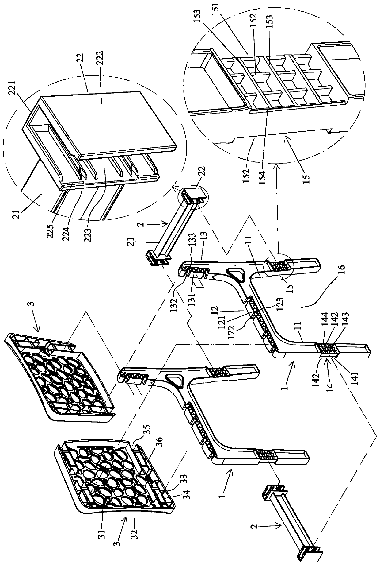
Figure 1 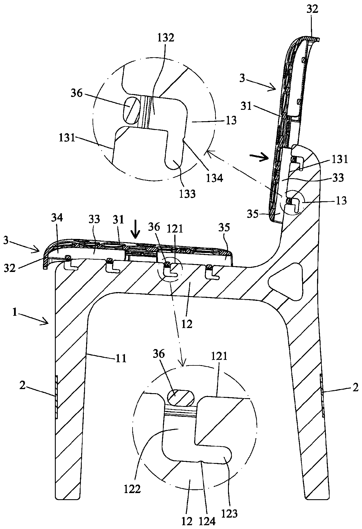
Figure 2 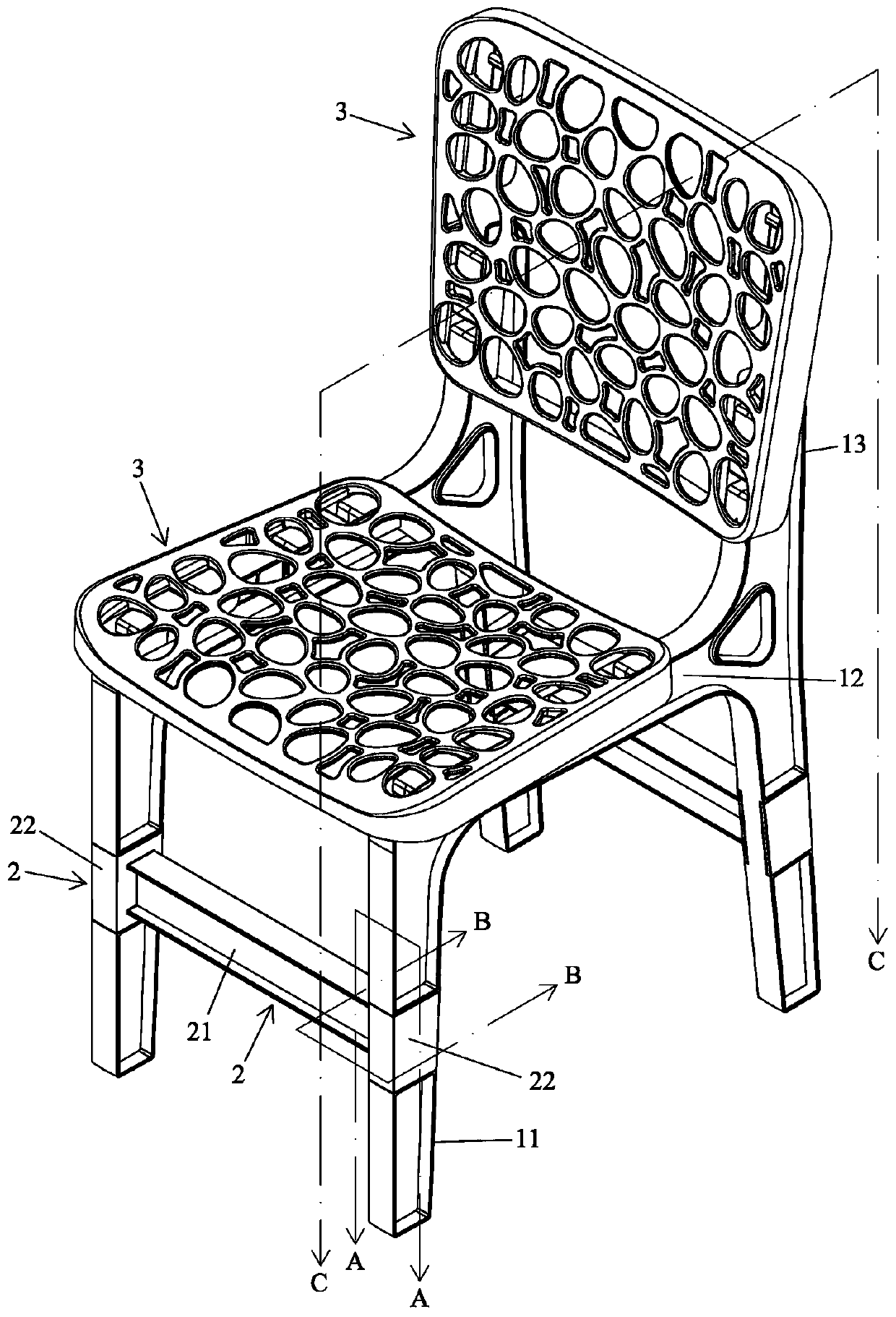
Figure 3
Abstract
Description
technical field
[0001] The present invention relates to a quick assembly chair, and mainly refers to a chair with modular manufacturing, simplified components, easy assembly and disassembly, and better assembly stability. Background technique
[0002] Chairs mainly include chair legs, chair seats, and chair back components. In order to reduce the volume, conventional chairs have a detachable and combined design. For example, the chair of TWM427069 includes two side frames made of metal tubes, two metal connecting rods, A plastic chair seat, a plastic chair back panel, the two side frames protrude from the inner side with a female part, the two connecting rods are provided with a male part that can pass through the female part at both ends, and the female part and the male part are connected to each other. Engagement holes are arranged on the top, and the seat seat is provided with hooking edge parts that can hook the connecting rods, and the hooking edge parts are provided w...
Examples
Embodiment Construction
[0045] In order to further explain the technical solution of the present invention, the present invention will be described in detail below through specific examples.
[0046] see Figure 1 to Figure 6, the present invention comprises a tripod 1, two connecting rods 2, and two boards 3. The tripod 1 is formed by plastic and is arranged oppositely. The straight bar part 11, the front and rear straight bar parts 11 are provided with a horizontal bar part 12 corresponding to the front and rear horizontal directions of the ground, and a pair of horizontal bar parts 12 corresponding to the upper and lower vertical directions of the ground is arranged on the rear direction of the bar part 12. The back rod part 13, the front and rear straight rod parts 11 are respectively provided with first and second joint parts 14 and 15, and the front side and the left and right sides of the first joint part 14 are respectively provided with a first front concave part 141 and two first front conc...