
A moving device with a ladder function for smart homes
A technology of smart home and handling device, applied in the field of intelligent robots, can solve the problems of low practicability, broken and damaged items, etc., and achieve the effect of safe handling
Patent Information
- Authority / Receiving Office
- CN · China
- Patent Type
- Patents(China)
- Current Assignee / Owner
- Publication Date
- 2019-04-12
Smart Images
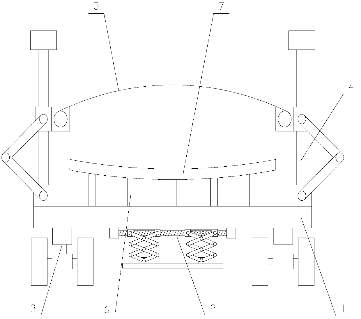
Figure 1 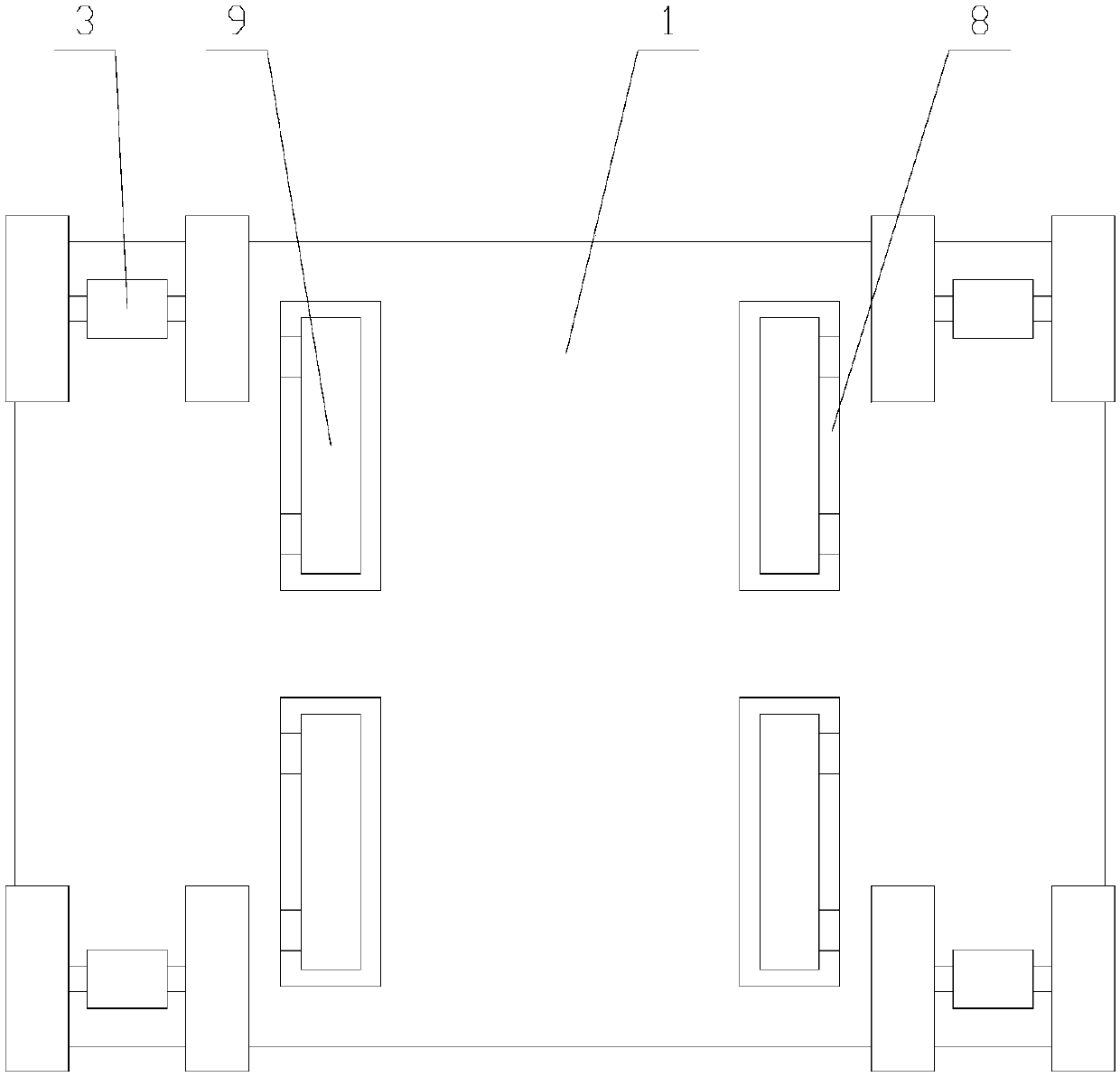
Figure 2 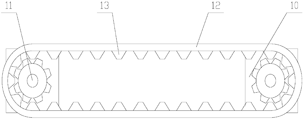
Figure 3
Abstract
Description
technical field
[0001] The invention relates to the field of intelligent robots, in particular to a carrying device with a ladder-climbing function for smart homes. Background technique
[0002] The reason why an intelligent robot is called an intelligent robot is because it has a well-developed "brain". What works in the brain is the center, the computer that has a direct connection to the person who operates it. Most importantly, such a computer can perform purposeful actions. It is for this reason that we say that such robots are real robots, even though they may differ in appearance.
[0003] With the advancement and development of science and technology, intelligent robots have been used in all walks of life to replace people to perform corresponding operations. In people's smart home life, it is usually necessary to carry some household equipment. At this time, intelligent robots can replace people to perform corresponding handling operations, especially when carryi...
Examples
Embodiment Construction
[0029] The present invention is described in further detail now in conjunction with accompanying drawing. These drawings are all simplified schematic diagrams, which only illustrate the basic structure of the present invention in a schematic manner, so they only show the configurations related to the present invention.
[0030] Such as Figure 1-Figure 6 As shown, a carrying device with a ladder function for smart homes, including a base 1, a pallet 7, a fastening mechanism, two support units 2, four mobile units 3 and several pillars 6, the support unit 2 and the mobile unit 3 are all arranged below the base 1, the fastening mechanism and the supporting plate 7 are all arranged above the base 1, the pillars 6 are evenly distributed between the base 1 and the supporting plate 7, the pillars 6 The bottom end is fixed on the base 1, and the top end of the pillar 6 is fixed on the supporting plate 7;
[0031] Described fastening mechanism comprises several fastening components, a...