
Handheld POS machine
A POS machine and hand-held technology, which is applied in the field of bank payment, can solve the problems of limited use time and range of hand-held POS machines, lithium batteries cannot be charged in time, outdoor fast payment troubles and other problems, and achieve real-time fast payment, simple structure and low cost. low effect
Patent Information
- Authority / Receiving Office
- CN · China
- Current Assignee / Owner
- Publication Date
- 2017-10-20
- Estimated Expiration
- Not applicable · inactive patent
Smart Images
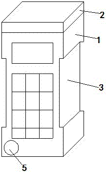
Figure 1 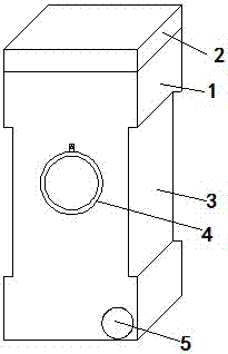
Figure 2 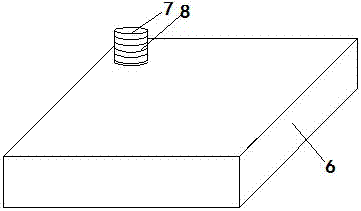
Figure 3
Abstract
Description
technical field
[0001] The invention relates to a hand-held POS machine, which belongs to the technical field of bank payment. Background technique
[0002] With the continuous progress and development of society, the increasing level of science and technology, and the continuous changes in the payment methods of people's consumption, more and more consumers use POS machines to swipe their bank cards for payment.
[0003] At present, some portable hand-held POS machines have also appeared, so that card swiping consumption is no longer limited to fixed places, and a fast payment method is realized anytime and anywhere. However, the power supply of the current handheld POS machine is generally a rechargeable lithium battery. When the handheld POS machine is used outside for a long time, the lithium battery has the problem that it cannot be charged in time, which greatly limits the use time limit of the handheld POS machine. And range, has brought big trouble to quick outdoor ...
Examples
Embodiment Construction
[0017] The present invention will be further described below in conjunction with the accompanying drawings.
[0018] Such as Figure 1~Figure 3 As shown, a hand-held POS machine includes a POS machine body 1, a wireless transmission module 2 is arranged on the top of the POS machine body 1, and a groove 3 for easy hand-holding is arranged in the middle of the POS machine body 1. 3 is provided with a finger ring 4, a charging hole 5 is provided at a corner of the bottom end of the POS machine body 1, a low-voltage winding is provided in the charging hole 5, and a wireless charger 6 is provided with a The charging column 7 is provided with a high-voltage winding 8 on the charging column 7, the high-voltage winding 8 is connected to the power storage module located in the wireless charger 6, and the low-voltage winding is connected to the power storage module located in the POS machine body 1 connected to the charging circuit.
[0019] The wireless transmission module 2 include...