
Temporary power supply for distribution automation terminal equipment and its usage method
A technology of power distribution automation and terminal equipment, which is applied in emergency power supply arrangements, battery circuit devices, lighting and heating equipment, etc., can solve problems such as offline and loss of protection functions, achieve flexible assembly and disassembly, improve power generation efficiency, and avoid power outages on lines The effect of the increase in the number of times and terminal device offline rate
Patent Information
- Authority / Receiving Office
- CN · China
- Patent Type
- Patents(China)
- Current Assignee / Owner
- Publication Date
- 2020-03-31
- Estimated Expiration
- Not applicable · inactive patent
Smart Images
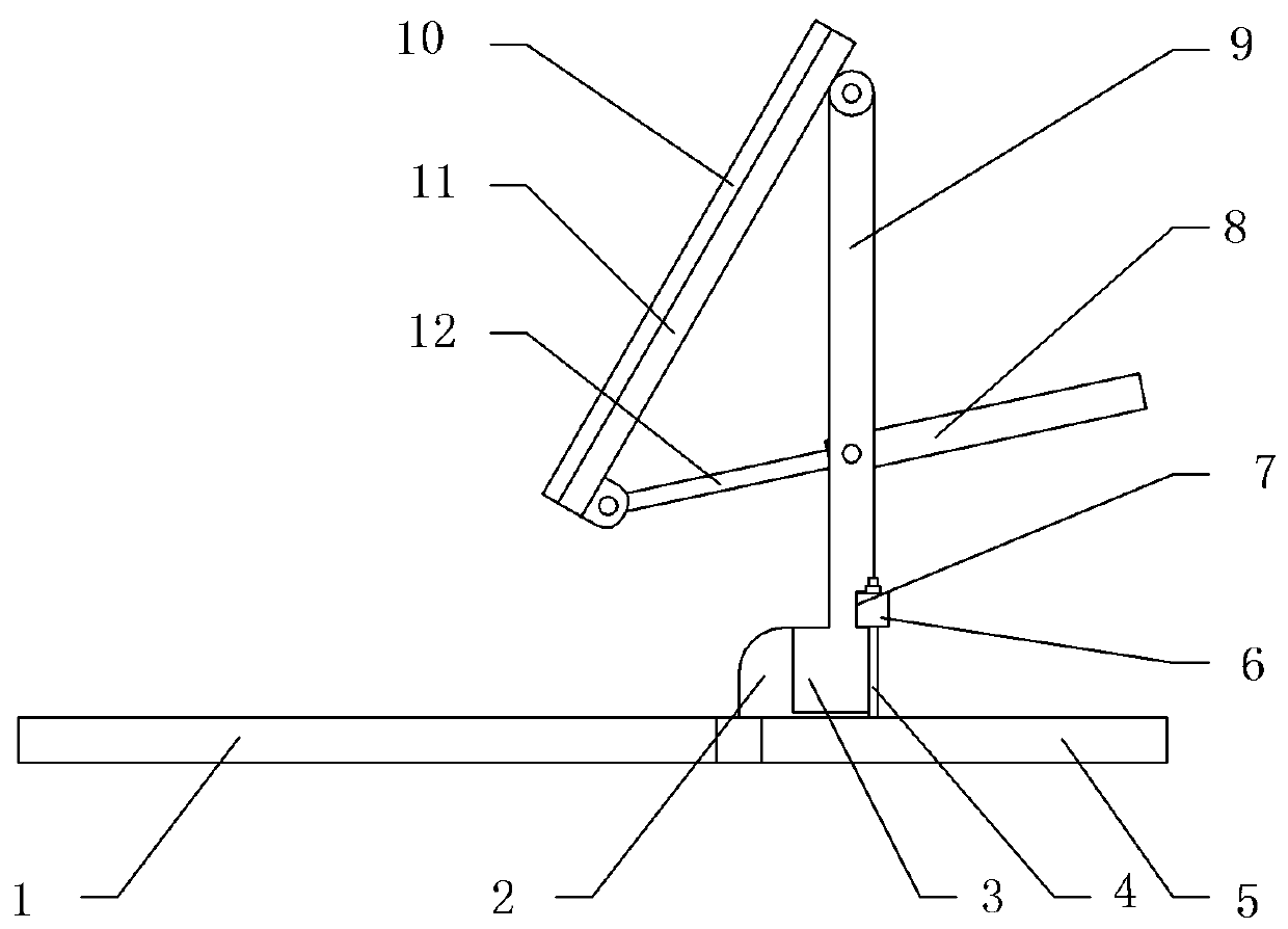
Figure 1 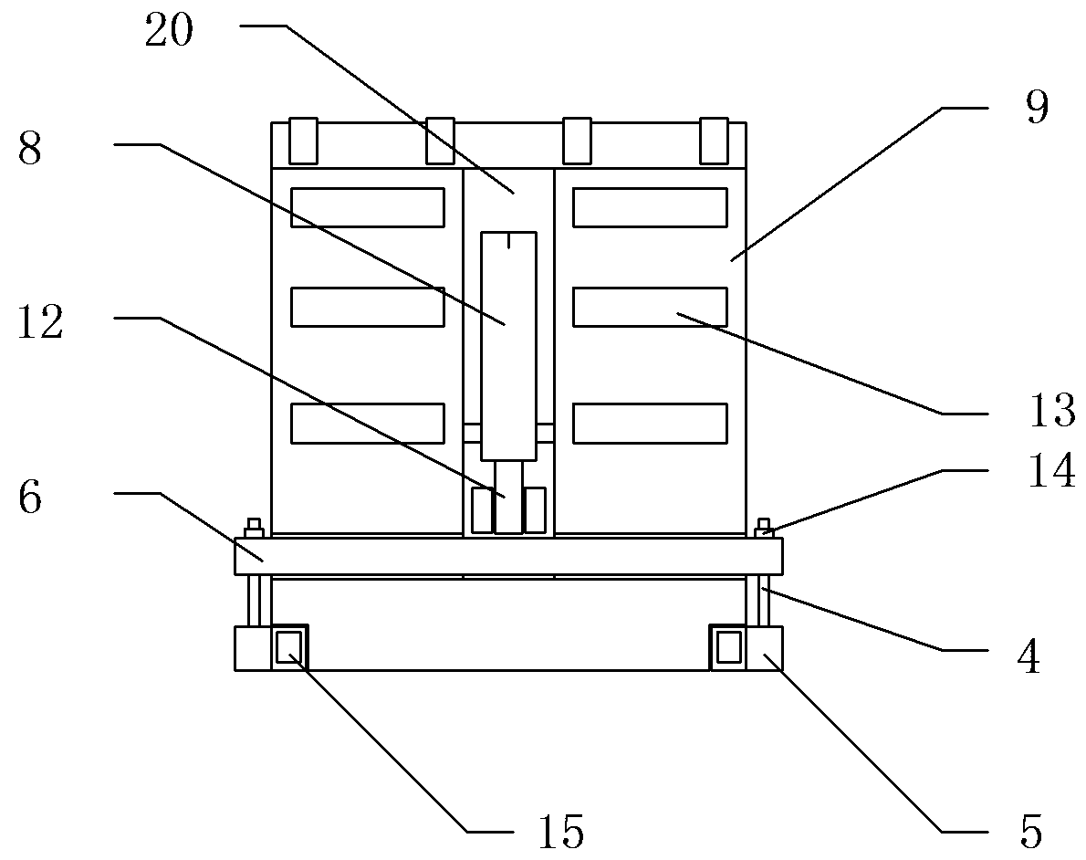
Figure 2 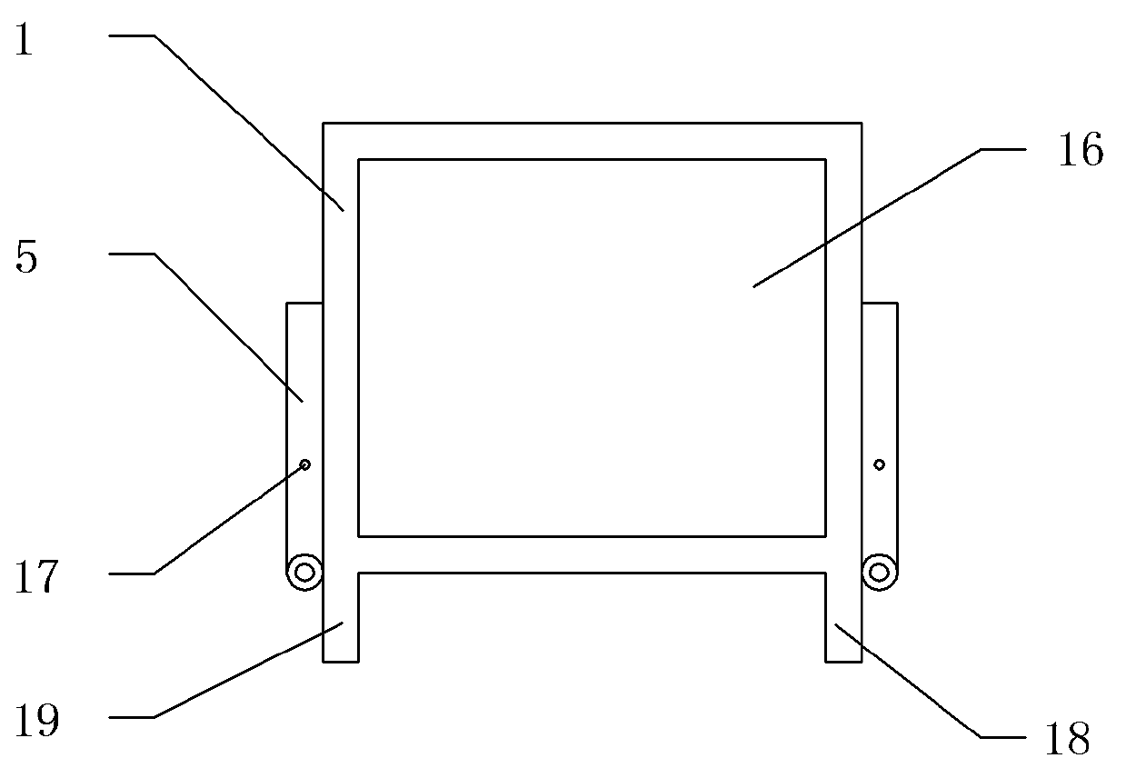
Figure 3
Abstract
Description
technical field
[0001] The invention relates to the field of electrical equipment, in particular to a temporary power supply for power distribution automation terminal equipment and a method for using the same. Background technique
[0002] The existing power distribution automation terminal equipment normally uses PT AC power supply mode. When a line failure occurs or a PT burns out to cause a power outage, it will be temporarily powered by the battery for no more than two days. After the battery runs out of power, the terminal will be offline. And lose all protective functions. Contents of the invention
[0003] The technical problem to be solved by the present invention is to overcome the above defects, provide a temporary power supply for power distribution automation terminal equipment and its use method, reduce the offline rate of power distribution terminals and the number of power outages caused by line equipment failures such as line PTs, and improve power supply ...
Examples
Embodiment 1
[0035] like Figures 1 to 3 As shown, the temporary power supply for the distribution automation terminal equipment includes an equipment box 3. A bracket 9 and a mounting plate 11 are provided on the rear side of the upper part of the equipment box 3. The upper part of the mounting plate 11 is hinged with the upper part of the bracket 9. solar panels10.
[0036] A tool box 13 is provided on the bracket 9 .
[0037] A battery is arranged inside the equipment box 3 , and the battery is electrically connected to the solar panel 10 .
[0038] A driving device for driving the mounting plate 11 is provided between the bracket 9 and the mounting plate 11 . The driving device includes a cylinder 8 and a push rod 12 , and one end of the cylinder 8 close to the push rod 12 is hinged to the bracket 9 . The end of the push rod 12 is hinged to the bottom of the mounting plate 11 .
[0039] The support 9 is provided with a vertical groove 20, and the cylinder 8 and the ejector rod 12 a...
Embodiment 2
[0046] The method for using the temporary power supply of distribution automation terminal equipment includes the following steps:
[0047] A. Before use:
[0048] A1, loosen the screw rod 4 or the nut 14, unfold the base plate 1, and the base plate 1 is set horizontally at this time;
[0049] A2, unfold the support rod 5,
[0050] A3, use the screw rod 4 and the nut 14 to connect the support rod 5 and the fixed beam 6;
[0051] A4, start the cylinder 8, and the solar panel 10 is launched;
[0052] A5, connect the storage battery with the distribution automation terminal equipment.
[0053] B. After use:
[0054] B1, disconnect the battery from the distribution automation terminal equipment;
[0055] B2, start the driving device, and the solar panel 10 is put away;
[0056] B3, loosen the screw rod 4 or the nut 14, and put away the support rod 5;
[0057] B4, put away the bottom plate 1, and now the bottom plate 1 is set vertically;
[0058] B5, use the screw rod 4 and...