
A traction-type straw tumbling and desoiling machine
A soil remover and traction technology, which is applied in the field of traction straw soil removal machine, can solve the problems of large soil content, high moisture content of straw, uneven moisture content of straw, etc., and achieve the effect of saving energy
Patent Information
- Authority / Receiving Office
- CN · China
- Patent Type
- Patents(China)
- Current Assignee / Owner
- Publication Date
- 2019-04-12
Smart Images
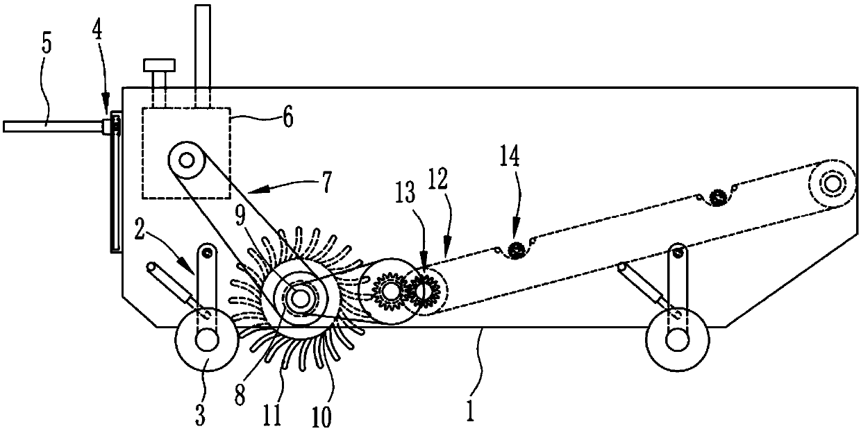
Figure 1 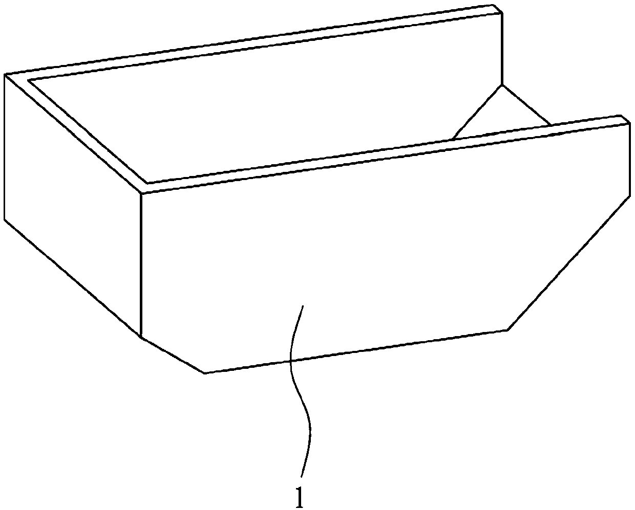
Figure 2 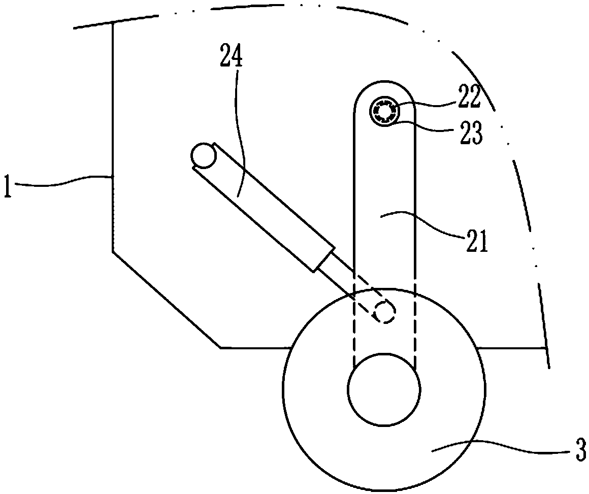
Figure 3
Abstract
Description
technical field
[0001] The invention relates to a straw tumbling and desoiling machine, in particular to a traction-type straw tumbling and desoiling machine. Background technique
[0002] my country has a large land area, high yield of crop straw, and low comprehensive utilization capacity. This is a common problem. As far as Heilongjiang Province is concerned, with the continuous increase in crop production. With the gradual liberalization of the ethanol processing industry and the recognition by growers of the relatively high benefits of corn, the area of corn will expand in some areas while achieving restorative growth, and the increase in straw has become an indisputable fact.
[0003] At present, there are shortcomings in the collection of field crop straws, such as large soil content, high straw moisture content, and uneven collection of straw moisture. Therefore, it is urgent to develop a method that can reduce straw soil content, straw moisture content, and even...
Examples
Embodiment 1
[0043] A traction-type straw tumbling and desoiling machine, such as Figure 1-11 As shown, it includes a frame 1, a height adjustment system 2, a ground wheel 3, a connecting mechanism 4, a traction frame 5, an engine 6, a transmission system 7, a first bearing seat 8, a first rotating shaft 9, a drum 10, and a feeding bomb. Teeth 11, conveying system 12, reversing system 13 and shaking system 14; the ground wheel 3 is connected to the frame 1 through the height adjustment system 2, the traction frame 5 is fixed to one side of the frame 1 through the connecting mechanism 4, and the engine 6 is installed On the side near the traction frame 5 in the frame 1, the first bearing seat 8 is embedded on the front and rear side walls of the frame 1; the first rotating shaft 9 is pivotally connected with the first bearing seat 8, and the front end of the first rotating shaft 9 is driven The system 7 is connected to the output end of the engine 6 by transmission; the drum 10 is fixedly ...