
Life saving equipment
A technology of life-saving equipment and main body, applied in the field of high-rise escape, can solve the problems of casualties, no high-rise escape or rescue device, and people unable to escape in time, and achieves the effect of convenient operation and simple structure
Patent Information
- Authority / Receiving Office
- CN · China
- Patent Type
- Applications(China)
- Current Assignee / Owner
- Publication Date
- 2018-11-02
- Estimated Expiration
- Not applicable · inactive patent
Smart Images
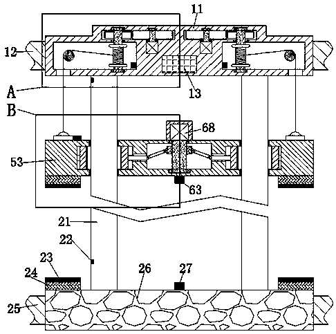
Figure 1 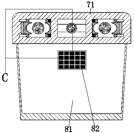
Figure 2 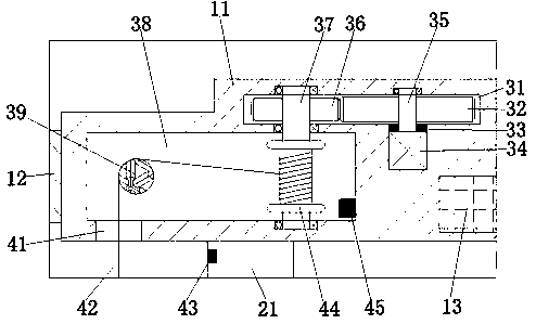
Figure 3
Abstract
Description
technical field
[0001] The invention relates to the technical field of high-rise escape, in particular to a lifesaving device. Background technique
[0002] Nowadays, the urban population is increasing year by year. In order to provide housing for more and more people in a city with a certain area, the method adopted in urban planning is to build higher floors than before to provide housing for more people. However, when high-rise buildings occur In the event of a fire, because the floors are high and the elevators cannot be used normally when a fire breaks out, it is often encountered that people trapped on high floors cannot escape in time, and there is no effective high-rise escape or rescue device, so the firefighters cannot arrive in time Or failure to rescue in time may cause casualties. Therefore, when a fire occurs, a device that can quickly descend from the upper floor to the bottom of the building without fire rescue is designed, which is a kind of high-rise life-s...
Examples
Embodiment Construction
[0018] Such as Figure 1-Figure 5As shown, a lifesaving equipment of the present invention includes a first device main body 11, a lifting device arranged in the first device main body 11, a safety device arranged on the lifting device, and a safety device arranged in the first device. The storage battery 13 in the main body 11, the lifting device includes a lifting cavity 38 symmetrically arranged in the main body 11 of the first device. Cavity 31, the lower inner wall of the drive cavity 31 is fixed with a lift motor 34, the upper side of the lift motor 34 and is located in the drive cavity 31 is provided with a driving drive gear 32, the shaft of the drive drive gear 32 A first driving wheel shaft 35 is fixedly arranged at the center, the lower end of the first driving wheel shaft 35 is dynamically connected to the lifting motor 34, and the lower end of the first driving wheel shaft 35 is between the lower inner walls of the driving chamber 31 A first seal ring 33 is provi...