
Novel weeding machine with weed collecting function
A weeding machine and function technology, applied in the field of new weeding machines, can solve the problems of reducing the work efficiency of operators, increasing the workload of the staff, inconvenient use, etc., achieving convenient collection and crushing operations, saving workload, and convenient collection. Effect
Patent Information
- Authority / Receiving Office
- CN · China
- Patent Type
- Applications(China)
- Current Assignee / Owner
- Publication Date
- 2018-11-16
Smart Images
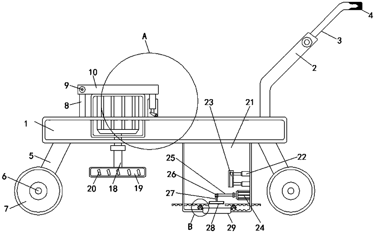
Figure 1 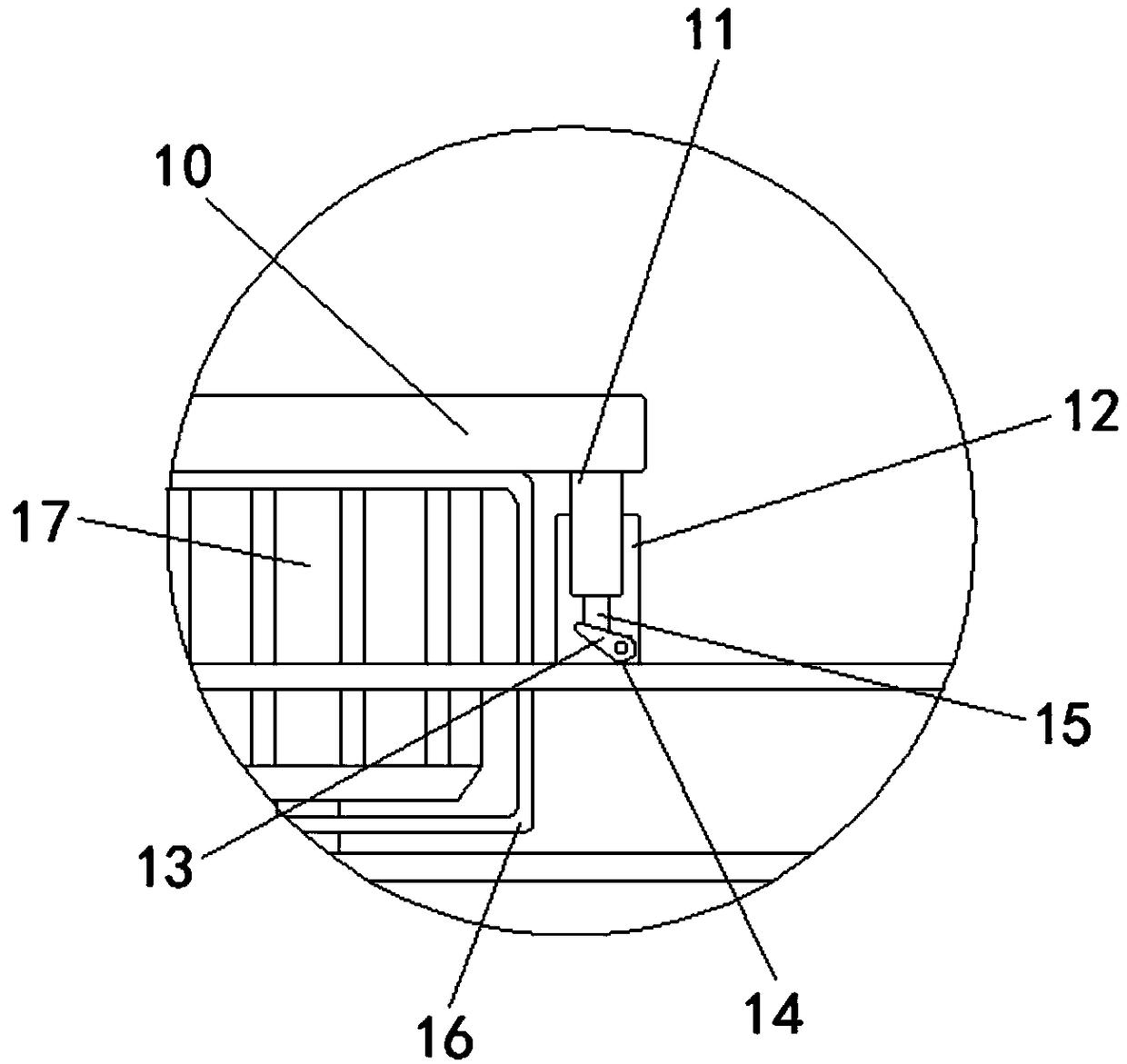
Figure 2 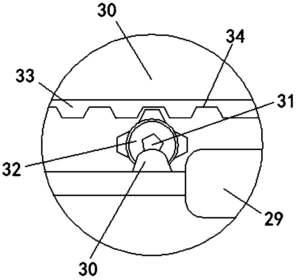
Figure 3
Abstract
Description
technical field
[0001] The invention relates to the technical field of agricultural machinery, in particular to a novel weeder with the function of collecting forage. Background technique
[0002] Lawnmower is also called weeder, lawnmower and lawn trimmer, etc. Lawnmower is a mechanical tool used to trim lawns and vegetation. It is composed of the control part, the cutter head is installed on the walking wheel, the engine is installed on the cutter head, and the output shaft of the engine is equipped with a blade. The blade uses the high-speed rotation of the engine to increase the speed a lot, which saves the working time of the weeding workers and reduces a lot. human resources.
[0003] However, the existing weeding machines leave a field of forage after weeding, which greatly affects the appearance. The staff also need to spend extra time cleaning the forage, which wastes time, reduces the work efficiency of the operator, and increases the number of staff. The workloa...
Examples
Embodiment Construction
[0029] The following will clearly and completely describe the technical solutions in the embodiments of the present invention with reference to the accompanying drawings in the embodiments of the present invention. Obviously, the described embodiments are only some, not all, embodiments of the present invention. Based on the embodiments of the present invention, all other embodiments obtained by persons of ordinary skill in the art without making creative efforts belong to the protection scope of the present invention.
[0030] see Figure 1-4, a new type of weeder with the function of collecting forage, including a horizontal plate 1, a connecting rod 2 is fixedly installed on the top right side of the horizontal plate 1, and a handrail 3 is fixedly installed on the side of the connecting rod 2 away from the horizontal plate 1, The outer cover of the handrail 3 is provided with a protective cover 4, and both sides of the bottom of the installation horizontal plate 1 are fixed...