
Double-precision optical regulation transmission device
A transmission device and optical adjustment technology, applied in optics, optical components, instruments, etc., can solve the problems of interference efficiency adjustment, harmful effects of beam alignment adjustment, and low adjustment efficiency, so as to improve adjustment stability and increase adjustment efficiency Effect
Patent Information
- Authority / Receiving Office
- CN · China
- Patent Type
- Applications(China)
- Current Assignee / Owner
- Publication Date
- 2018-11-27
- Estimated Expiration
- Not applicable · inactive patent
Smart Images
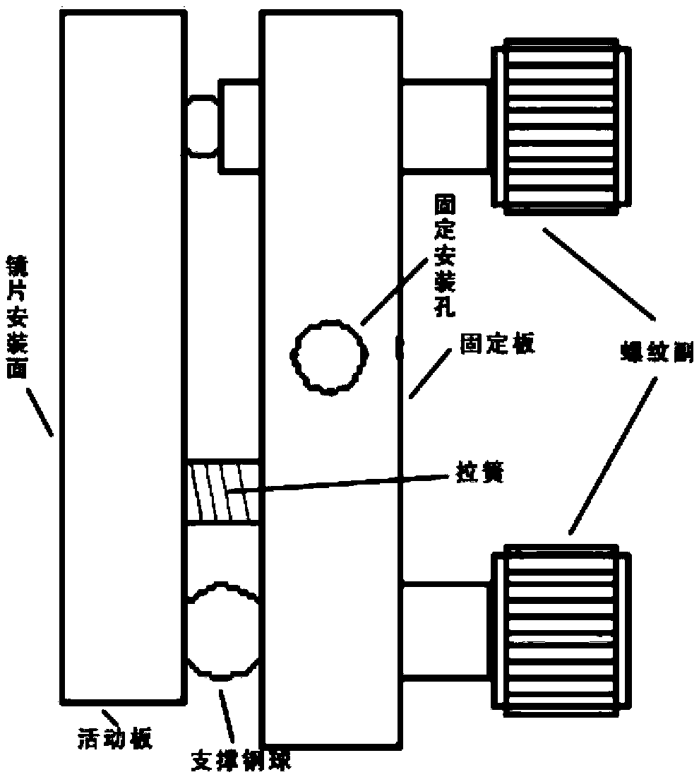
Figure 1 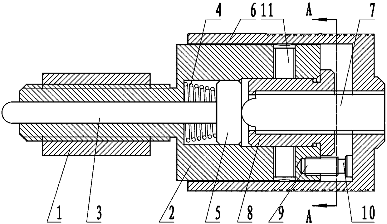
Figure 2 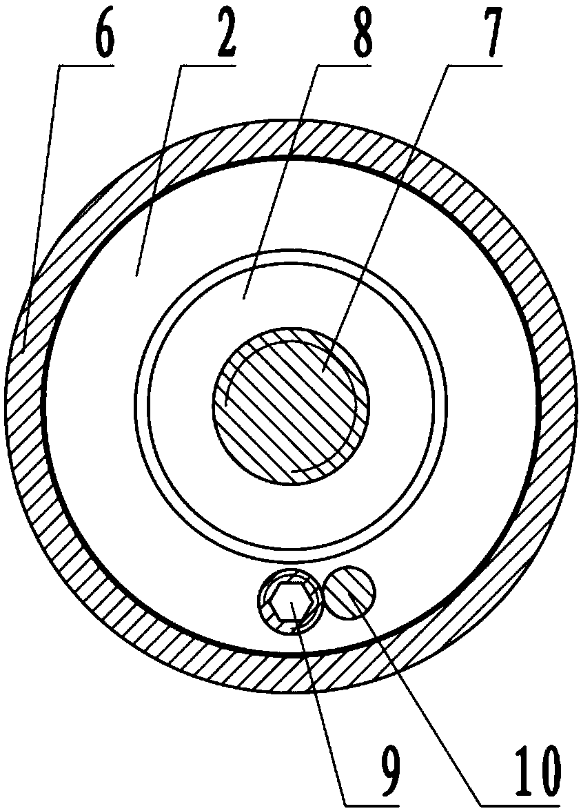
Figure 3
Abstract
Description
technical field
[0001] The invention relates to an installation and adjustment device of an optical element, system or instrument, in particular to a double-precision optical adjustment transmission device. Background technique
[0002] At present, the known precision optical adjustment mount (see attached figure 1 ) includes two functions of angle adjustment and translation adjustment, figure 1 Shown is a general-purpose solution for the two-dimensional angle adjustment frame, which mainly includes several parts shown in the figure. The fixed plate is generally fixed on the equipment through the installation hole. When adjusting one dimension rotation, by rotating one of the thread pairs, the thread The auxiliary nut is fixed on the fixed plate. The front end of the threaded auxiliary screw is a hemisphere. When the threaded auxiliary screw is rotated, the threaded auxiliary screw moves forward while rotating, pushing the movable plate to rotate around the supporting steel...
Examples
Embodiment Construction
[0020] see figure 2 And and 3, the double-precision optical adjustment transmission device of the present invention includes a coarse-threaded nut 1 fixed on the optical adjustment frame and a coarse-threaded screw 2 threadedly connected with the coarse-threaded nut 1 .
[0021] The described coarse tooth screw 2 is provided with a center hole along its axial direction, and a ball head polished rod 3 that is a ball head is installed in the center hole in a moving fit. The other end of the head expands into a chamber, and the chamber is provided with a compression spring 4, a slider 5 and a fine thread nut 8 in sequence along the ball head direction away from the polished rod 3 of the ball head; wherein, the compression spring 4 wears Located outside the polished ball rod 3, the slider 8 is connected to the polished rod 3, and the fine thread nut 8 and the coarse thread screw 2 are in contact with each other, and two anti-slip screws 11 are provided to prevent slippage. Screw...