
Hydraulic type door closer capable of stopping door
A door closer, hydraulic technology, applied in the direction of the fastening device of the wing leaf, the switch device with the brake device, the door/window accessories, etc., can solve the problem that the ordinary door closer does not have the function of stopping the door The problem of laborious operation of the device and slow opening of the door can be solved, and the effect of improving the degree of automation and practicability of the equipment, beautiful appearance, and integration of the overall structure can be achieved.
Patent Information
- Authority / Receiving Office
- CN · China
- Patent Type
- Applications(China)
- Current Assignee / Owner
- Publication Date
- 2018-12-07
- Estimated Expiration
- Not applicable · inactive patent
Smart Images
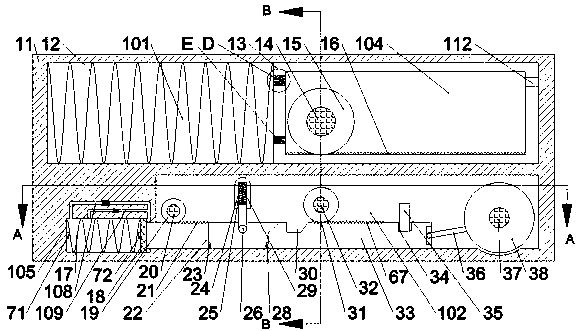
Figure 1 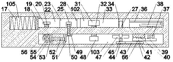
Figure 2 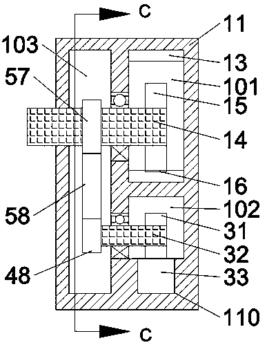
Figure 3
Abstract
Description
technical field
[0001] The invention relates to the field of home decoration, in particular to a hydraulic door closer capable of stopping the door. Background technique
[0002] In daily life, the action of opening and closing doors is often involved. In many cases, the door needs to be operated normally. However, most ordinary door closers do not have the function of stopping the door, and the installation on the surface of the door seriously affects the appearance. At the same time, ordinary door closers The operation is laborious and the door opening action is slow. This device solves this problem. Contents of the invention
[0003] The technical problem to be solved by the present invention is to provide a hydraulic door closer capable of stopping the door, which can solve the above-mentioned problems in the prior art.
[0004] The present invention is achieved through the following technical solutions: A hydraulic door closer capable of stopping the door of the pres...
Examples
Embodiment Construction
[0021] Such as Figure 1-Figure 6 As shown, a hydraulic door closer capable of stopping the door of the present invention includes a fuselage 11 and a first cavity 101 disposed in the fuselage 11, and a The second cavity 102 is located at the front side of the first cavity 101 to be provided with a third cavity 103, and a first slider 13 is provided to slide left and right in the first cavity 101, and the first slider 13 A first spring 12 is elastically arranged between the left end wall and the left end wall of the first cavity 101, the first slider 13 is provided with a fourth cavity 104, and the lower end wall of the fourth cavity 104 is A first rack 16 is arranged inside, and a first rotating shaft 14 extending forward and backward is rotatably arranged between the fourth cavity 104 and the third cavity 103, and the rear end of the first rotating shaft 14 extends to The first gear 15 cooperating with the first rack 16 is fixedly installed in the fourth cavity 104 and at t...