

A damping type pilot control switch valve
A pilot control and damping technology, which is applied in the direction of servo motor components, mechanical equipment, fluid pressure actuators, etc., can solve the problems of increasing complexity, increasing the volume of switching valves, and reducing reliability.
Patent Information
- Authority / Receiving Office
- CN · China
- Patent Type
- Patents(China)
- Current Assignee / Owner
- Publication Date
- 2020-10-27
Smart Images
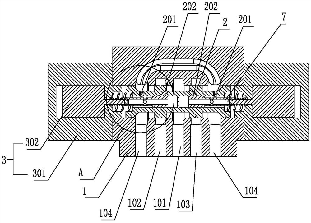
Figure 1 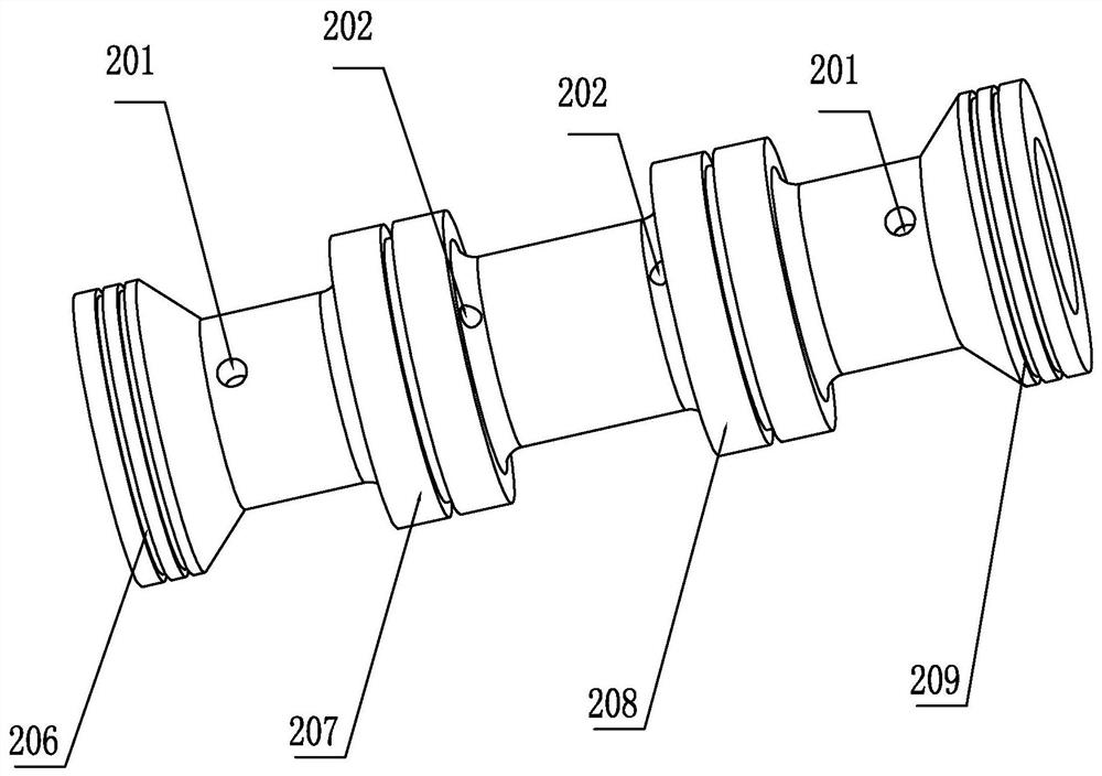
Figure 2 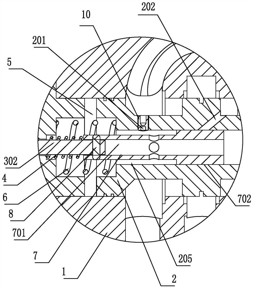
Figure 3
Abstract
Description
technical field
[0001] The invention belongs to the field of fluid transmission and control, and in particular relates to a damping type pilot control switch valve. Background technique
[0002] Fluid control valves, especially hydraulic valves, play the role of controlling flow, pressure and switching oil circuits. For example, the electromagnetic switching valve plays the role of controlling the flow and switching the oil circuit; the electromagnetic switching valve is divided into: single-stage valve (direct acting valve) and two-stage valve (pilot control valve) according to the flow capacity. In the industry standard, single-stage valves (direct-acting valves) are divided into 6 channels and 10 channels; two-stage valves (pilot control valves) are divided into 16, 25, 32... channels (the larger the number The larger the valve volume, the greater the flow capacity).
[0003] The fluid switching control valve used for small flow is generally in the form of a single-stag...
Examples
Embodiment 1
[0035] like figure 1As shown, a damping type pilot control switch valve includes a valve body 1 and a main valve core 2. The valve body 1 is provided with a high-pressure oil inlet 101, a first control oil port 102, a second control oil port 103, Two low-pressure oil outlets 104 (can be 0 pressure), two low-pressure oil outlets 104 are set on both sides, high-pressure oil inlet 101 is set in the middle, and the first control oil port 102 and the second control oil port 103 are respectively set Between the two low-pressure oil outlets 104 and the high-pressure oil inlet 101, such as figure 2 As shown, the main valve core 2 is provided with a first protruding ring 206, a second protruding ring 207, a third protruding ring 208, and a fourth protruding ring 209 in the circumferential direction, and the first protruding ring 206 and the fourth protruding ring 209 are respectively located at The two ends of the main spool 2 are in dynamic sealing cooperation with the valve body 1 ...
Embodiment 2
[0048] Such as Figure 5 As shown, a damping type pilot control switch valve includes a valve body 1 and a main valve core 2. The valve body 1 is provided with a high-pressure oil inlet 101, a first control oil port 102, a second control oil port 103, Two low-pressure oil outlets 104 (can be 0 pressure), two low-pressure oil outlets 104 are set on both sides, high-pressure oil inlet 101 is set in the middle, and the first control oil port 102 and the second control oil port 103 are respectively set Between the two low-pressure oil outlets 104 and the high-pressure oil inlet 101, the main valve core 2 is provided with a first protruding ring 206, a second protruding ring 207, a third protruding ring 208, and a fourth protruding ring 209 in the circumferential direction. The first protruding ring 206 and the fourth protruding ring 209 are respectively located at both ends of the main valve core 2 and are in dynamic sealing cooperation with the valve body 1 (the sealing performan...
Embodiment 3
[0057] Such as Figure 8 As shown, an inflow damping type pilot control on-off valve includes a valve body 1 and a main valve core 2. The valve body 1 is provided with a high-pressure oil inlet 101, a first control oil port 102, and a second control oil port. 103. Two low-pressure oil outlets 104 (can be 0 pressure), two low-pressure oil outlets 104 are set on both sides, high-pressure oil inlet 101 is set in the middle, the first control oil port 102, the second control oil port 103 respectively arranged between the two low-pressure oil outlets 104 and the high-pressure oil inlet 101, such as figure 2 As shown, the main valve core 2 is provided with a first protruding ring 206, a second protruding ring 207, a third protruding ring 208, and a fourth protruding ring 209 in the circumferential direction, and the first protruding ring 206 and the fourth protruding ring 209 are respectively located at The two ends of the main spool 2 are in dynamic sealing cooperation with the v...