
Heat dissipation composite cable
A composite cable and cable technology, applied in the direction of insulated cables, cables, circuits, etc., can solve problems such as poor compression resistance and heat dissipation performance, increased chance of being subjected to compression, and insufficient service life, etc., to achieve rapid heat dissipation and accelerated exchange , Good anti-stress effect
Patent Information
- Authority / Receiving Office
- CN · China
- Patent Type
- Patents(China)
- Current Assignee / Owner
- Publication Date
- 2020-08-11
Smart Images
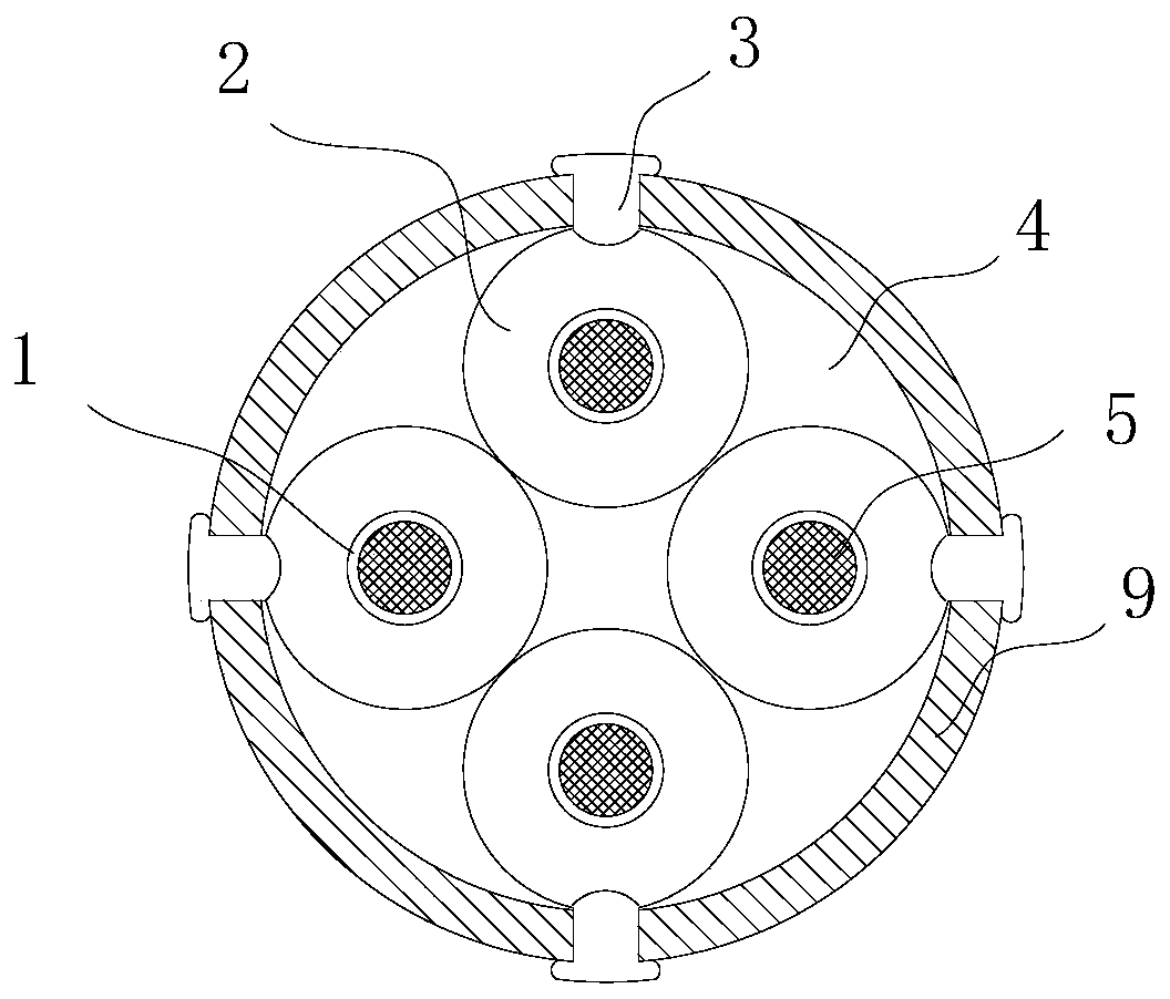
Figure 1 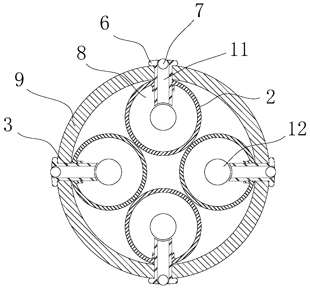
Figure 2 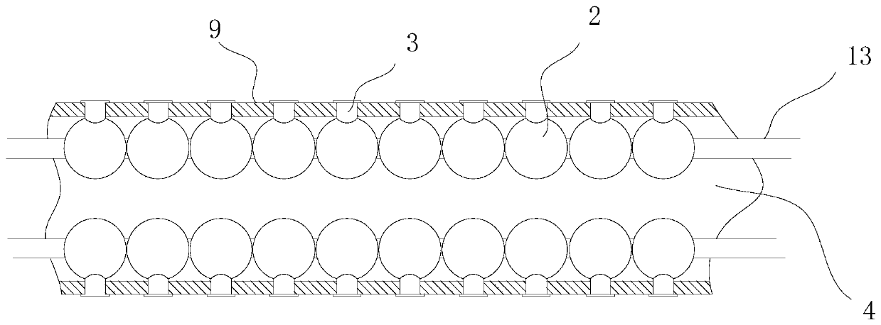
Figure 3
Abstract
Description
technical field
[0001] The invention relates to the field of cables, in particular to a heat dissipation composite cable. Background technique
[0002] In the prior art, the cable includes an outer layer and more than one strand of cable core wires inside, and the inside of the outer layer is a space that is connected to each other. Therefore, when a fire occurs in one of the cables, or one of the cables When local heat is generated, the cables will affect each other, which will lead to the damage of the entire cable, which has a safety impact.
[0003] Furthermore, since the inside of the outer layer is a closed space, it cannot exchange heat with the external environment. When under pressure, the inner core wire is directly damaged by pressure, so the compression resistance and heat dissipation performance are relatively poor, and the service life Cables that are not long enough, especially when they are in motion, will greatly increase their chances of being crushed. C...
Examples
Embodiment Construction
[0019] Such as figure 1 and figure 2 As shown, the heat dissipation composite cable includes an outer coating layer 9, a core wire installation cavity 4 is provided in the middle of the outer coating layer 9, and more than one through hole is respectively opened on the four sides of the core wire installation cavity 4, and each through hole is passed through. The holes are all loaded into a heat exchange tube 3, and there is a heat exchange channel 11 in the middle of the heat exchange tube 3, both ends of the heat exchange channel 11 are open, and one end of the heat exchange tube 3 protrudes from the outer layer through the through hole. 9, the inner end of the heat exchange tube 3 is inserted into an airbag ball 2, and a spherical cavity 8 is arranged in the airbag ball 2, and a metal ball 7 is arranged in the heat exchange channel 11 inside the heat exchange tube 3 ;
[0020] Each airbag ball 2 is provided with a core wire hole 12 in the same direction, and the core wir...