
Switching system for supplying power to emergency power supply
A switching system, backup power technology, applied in power network operating system integration, emergency power arrangement, information technology support system, etc. The effect of avoiding equipment damage, protecting the safety of use, and avoiding personal safety
Patent Information
- Authority / Receiving Office
- CN · China
- Patent Type
- Applications(China)
- Current Assignee / Owner
- Publication Date
- 2019-07-09
- Estimated Expiration
- Not applicable · inactive patent
Smart Images
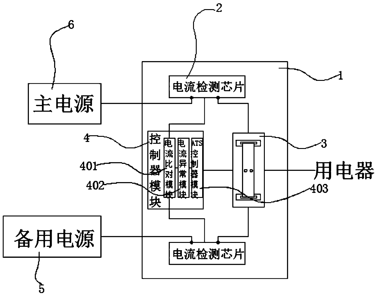
Figure 1 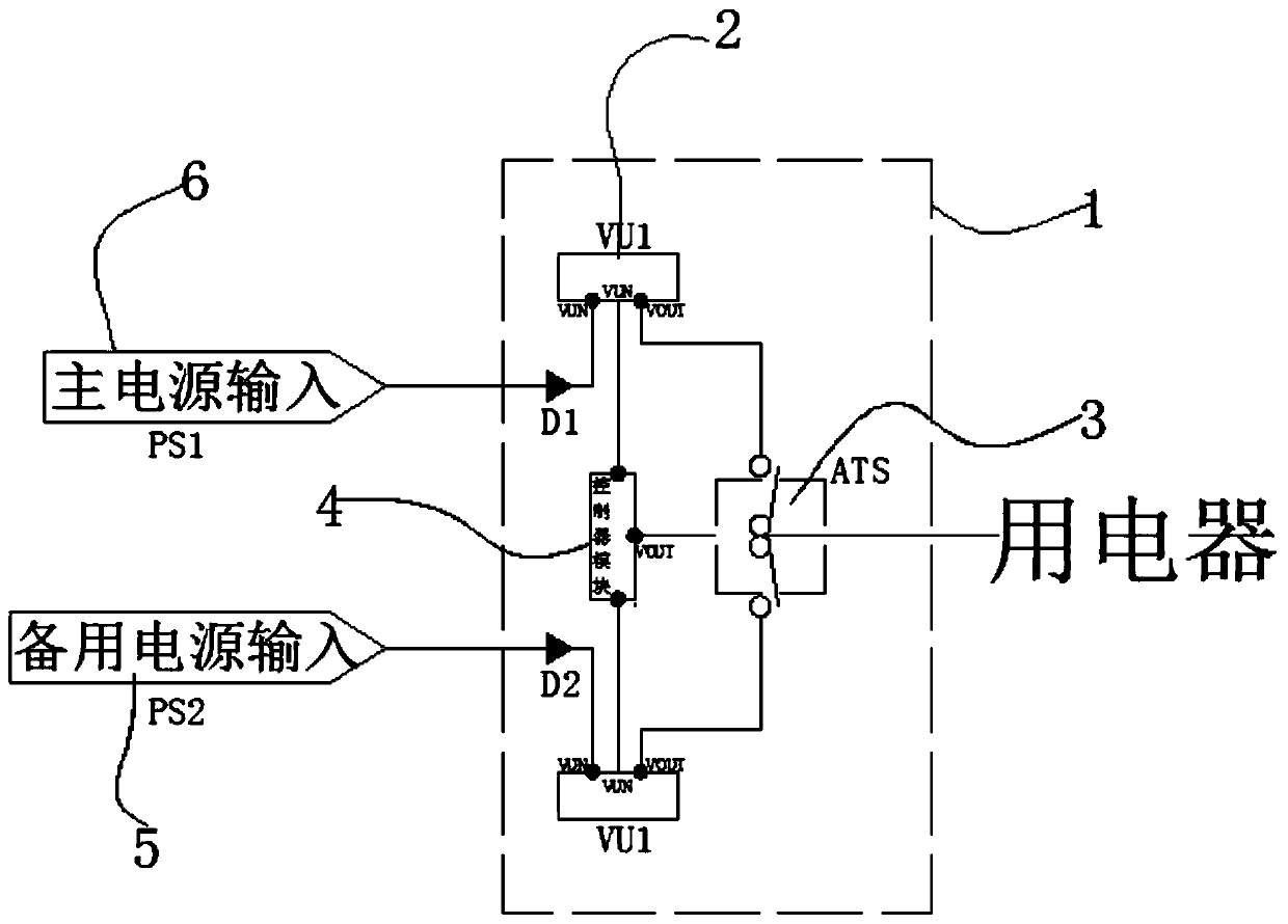
Figure 2 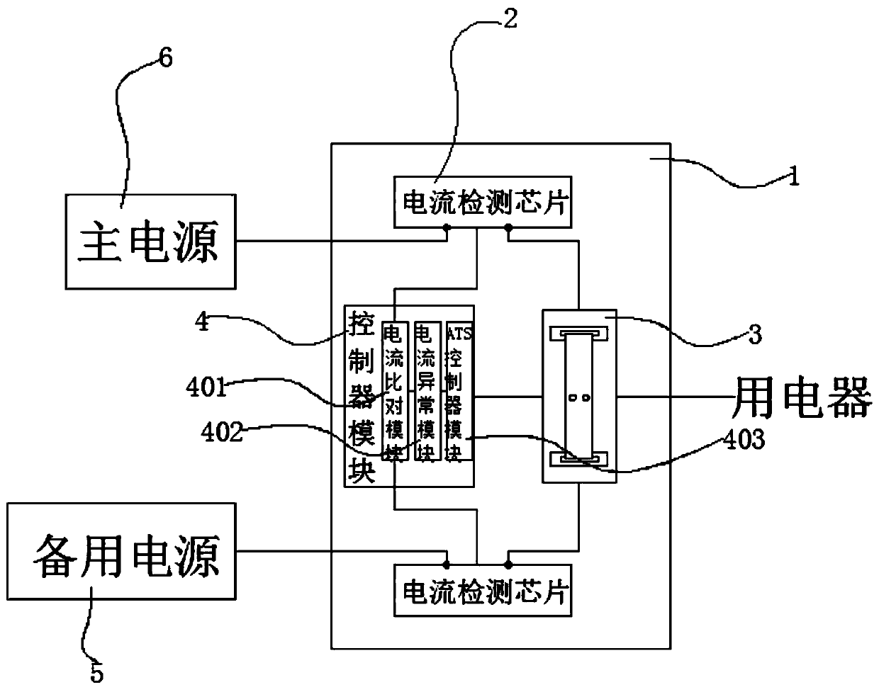
Figure 3
Abstract
Description
technical field
[0001] The invention belongs to the field of battery management systems, and in particular relates to a switching system for backup power supply. Background technique
[0002] Buildings with a higher level of power supply must be able to provide sufficient power under normal conditions, and have sufficient backup power when the normal power supply fails. When the building encounters an emergency (such as: fire, earthquake, etc.), There must also be emergency power to ensure disaster relief and evacuation. Any building needs to consume a lot of electricity to be able to use and operate normally. The main source of electricity consumed by buildings is the national or regional power grid. Supplementary power supply, in many cases, diesel generator sets and battery energy storage equipment will be set up as backup and emergency power supply.
[0003] At present, for equipment that does not allow power failure, the switch between the main power supply and the ba...
Examples
Embodiment 1
[0022] Such as Figure 1-2 As shown, a switching system for backup power supply, including a switching system 1, the switching system 1 internally includes an ATS automatic transfer switch 3 for switching between connecting circuits, and
[0023] The controller module 4 connected with the ATS automatic transfer switch 3 is used to control the switching work of the ATS automatic transfer switch 3, and
[0024] The current detection chip 2 connected with the controller module 4 is used to detect the strength of the current in the circuit, and
[0025] The main power supply 6 connected with the current detection chip 2 is used to provide electric energy, and
[0026] The standby power supply 5 connected with the current detection chip 2 is used to provide electric energy when the main power supply 6 is powered off.
[0027] The controller module 4 includes a current comparison module 401, an abnormal current module 402 and an ATS controller module 403; the current detection chi...