

Elastic wedge-caulking type flat gate valve
A flat gate valve, wedge type technology, applied in the direction of sliding valve, valve device, engine components, etc., can solve the wear of the sealing surface of the gate and the sealing surface of the valve seat, affect the sealing performance and service life of the product, and cannot be disconnected in time, etc. problems, to achieve the effect of reliable sealing performance, long service life and light opening and closing
Patent Information
- Authority / Receiving Office
- CN · China
- Patent Type
- Applications(China)
- Current Assignee / Owner
- Publication Date
- 2019-08-09
Smart Images
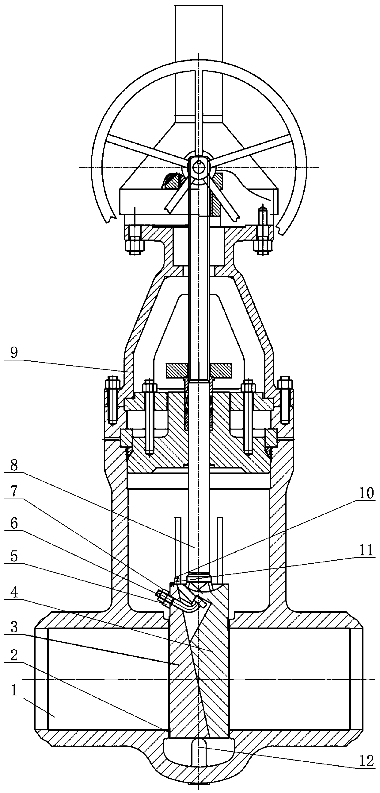
Figure 1
Abstract
Description
technical field
[0001] The invention belongs to the field of valves, in particular to a wedge-tight flat gate valve. Background technique
[0002] The wedge-tight slab gate valve is generally composed of a main gate and an auxiliary gate. The main gate and the auxiliary gate adopt a slope or a K-shaped slope to cooperate with each other. The main gate and the auxiliary gate are installed in the gate frame. , the main ram rises and separates from the inclined surface of the auxiliary ram, and then pulls the auxiliary ram to lift together. When the auxiliary ram is in place, it is wedged tightly by the inclined surface of the main ram and is tightly matched with the valve seat to reduce the opening and closing. The wear between the gate sealing surface and the valve seat sealing surface during the process. Its main disadvantage is that when the gate valve is closed for a long time, mutual adhesion is likely to occur between the slopes of the main gate and the auxiliary gate, ...
Examples
Embodiment Construction
[0010] Such as figure 1 The elastic wedge-tight slab gate valve shown includes a valve body 1, a valve seat 2, a gate plate, a valve stem 8, and a valve cover 9. The gate plate is composed of a main gate plate 4 and an auxiliary gate plate 3. The main gate plate 4 and the auxiliary gate plate The gates 3 are in contact with each other using inclined surfaces. The center of the upper end of the main gate 4 is connected to the lower end of the valve stem 8. The main gate 4 is fixedly connected to the axial direction of the valve stem 8, and radially movable relative to the valve stem 8. A limit plate 11 fixedly connected to the auxiliary ram 3 is provided above the main ram 4, and a limit adjusting screw 10 is provided on the limit plate 11, and the limit adjusting screw 10 axially adjusts the main ram 4 and the auxiliary ram 3 The radial eccentric movement distance between them, the axial adjustment mentioned here refers to the adjustment along the direction of the centerline o...