
An improved galvanized steel pipe
A galvanized steel pipe, an improved technology, applied in the direction of pipes/pipe joints/fittings, sleeves/sockets, passing components, etc., can solve the problems of easy errors in splicing, poor sealing effect, and easy leakage, etc., to achieve Easy installation and disassembly, enhanced tensile strength, and the effect of avoiding gap errors
Patent Information
- Authority / Receiving Office
- CN · China
- Patent Type
- Patents(China)
- Current Assignee / Owner
- Publication Date
- 2020-12-25
Smart Images
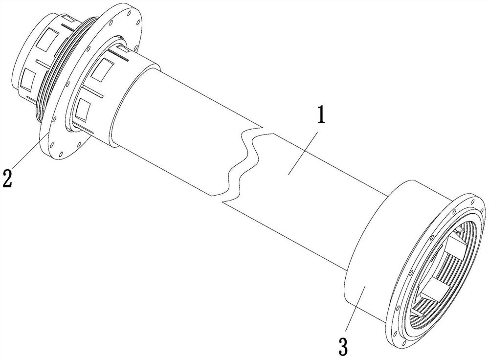
Figure 1 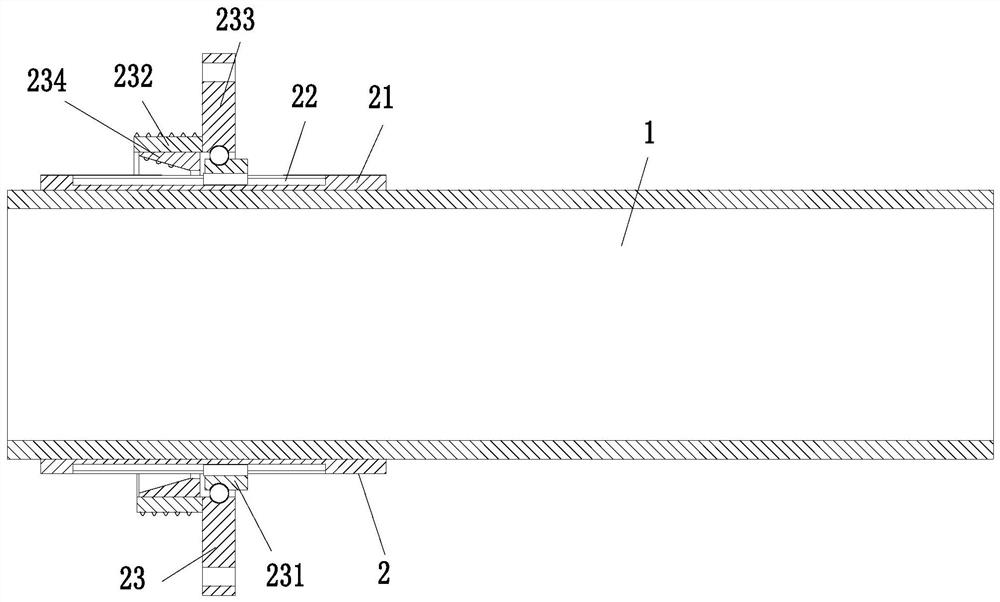
Figure 2 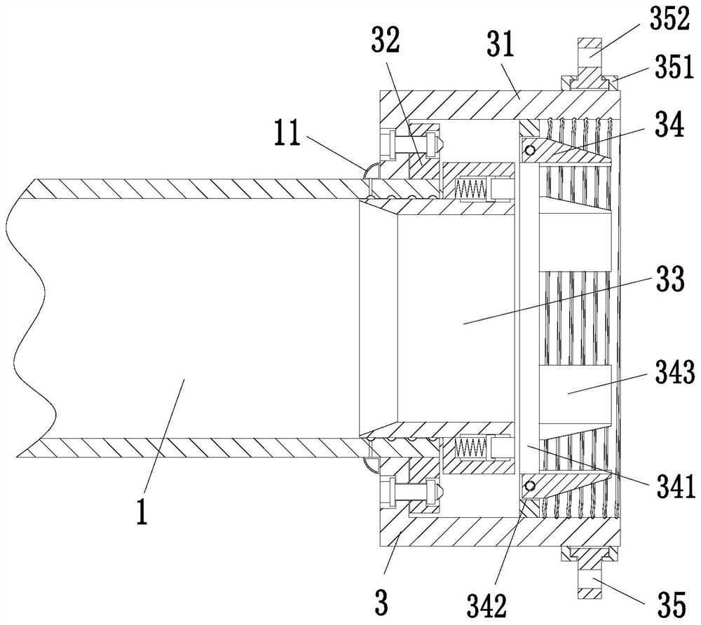
Figure 3
Abstract
Description
technical field
[0001] The invention relates to the field of galvanized steel pipes, in particular to an improved galvanized steel pipe. Background technique
[0002] Galvanized steel pipes are often used in pipeline systems for transporting petroleum and petroleum products. They are mainly composed of oil pipelines, oil stations and other auxiliary related equipment. For transportation equipment, compared with railway and highway oil transportation, which are also land transportation methods, pipeline oil transportation has the characteristics of large transportation volume, good airtightness, low cost and high safety factor.
[0003] At present, the existing oil-transporting galvanized steel pipes usually have the following defects in the splicing process: 1. The splicing effect of the existing galvanized steel pipes is poor when splicing, and the splicing is labor-intensive and time-consuming. At the same time, the sealing effect after the pipe connection is poor , the c...
Examples
Embodiment Construction
[0026] The embodiments of the present invention will be described in detail below with reference to the accompanying drawings, but the present invention can be implemented in many different ways defined and covered by the claims.
[0027] Such as Figure 1 to Figure 4 As shown, an improved galvanized steel pipe includes a pipe body 1, a fixing frame 2 and a connecting frame 3. The fixing frame 2 is fixedly installed on the left end of the pipe body 1, and the connecting frame 3 is installed on the right end of the pipe body 1.
[0028] The fixed frame 2 includes a fixed sleeve 21, a sliding groove 22 and a locking mechanism 23. The fixed sleeve 21 is installed on the left end of the pipe body 1 by welding, and the upper end of the fixed sleeve 21 is along its circumferential direction. Sliding grooves 22 are evenly arranged, and a locking mechanism 23 is arranged on the outside of the fixed sleeve 21. The locking mechanism 23 is connected with the sliding groove 22 through a s...