
A high-efficiency and total management device for propellant in a surface tension storage tank
A surface tension storage tank and management device technology, which is applied in jet propulsion devices, rocket engine devices, machines/engines, etc., can solve problems such as high maneuverability, high acceleration and large flow, and achieve excellent propellant management capabilities, Improved rigidity and mobility
Patent Information
- Authority / Receiving Office
- CN · China
- Patent Type
- Patents(China)
- Current Assignee / Owner
- Publication Date
- 2020-09-18
Smart Images
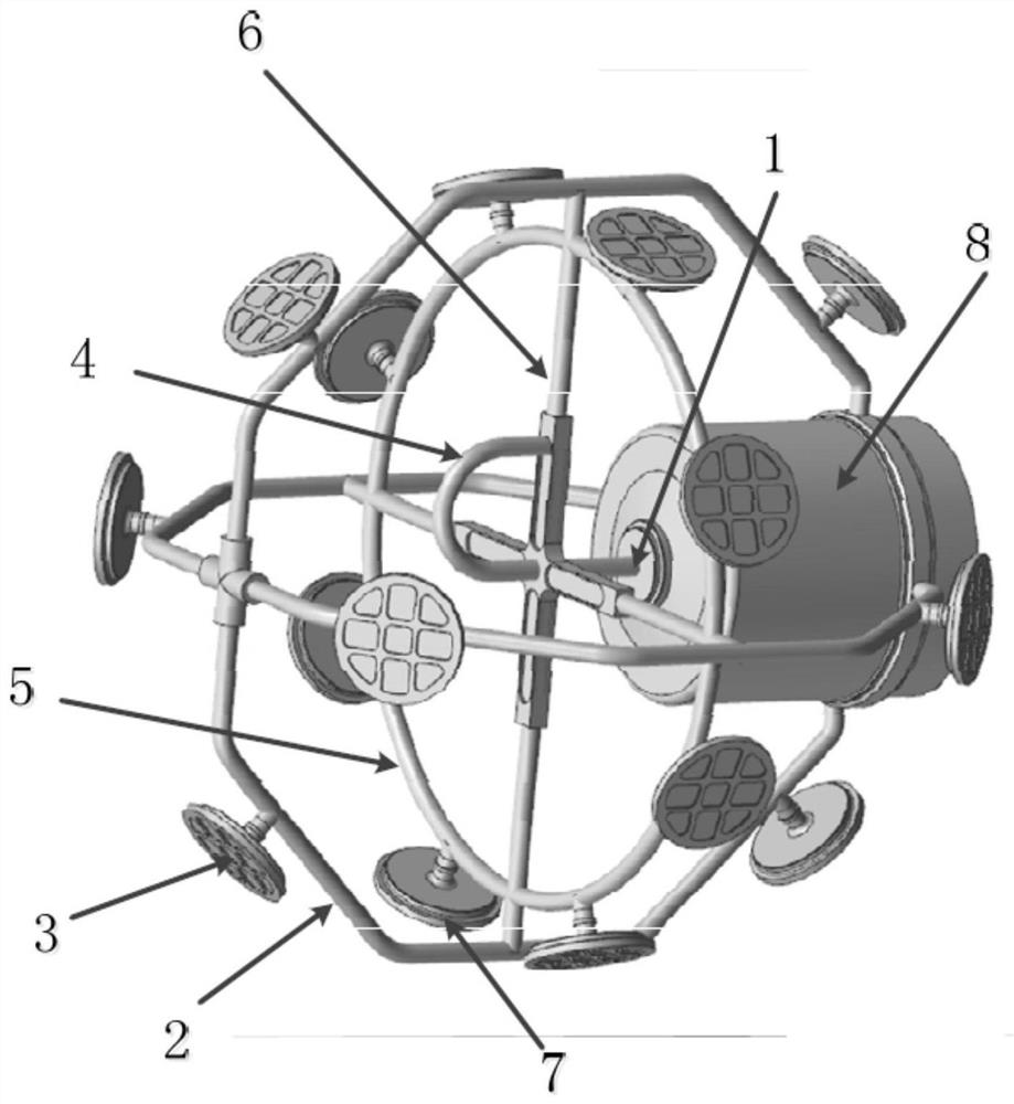
Figure 1 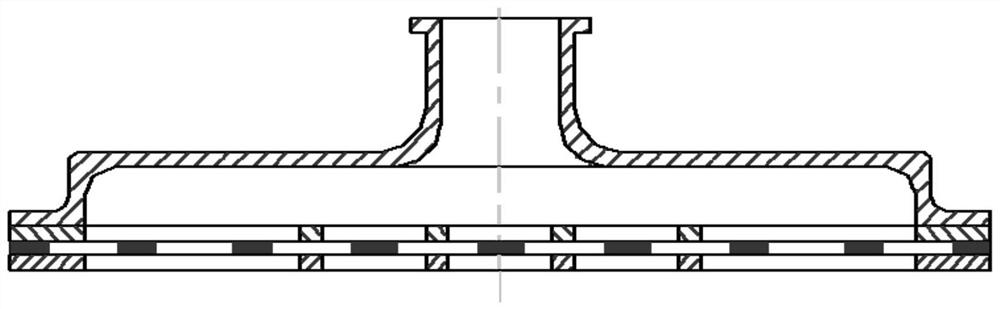
Figure 2 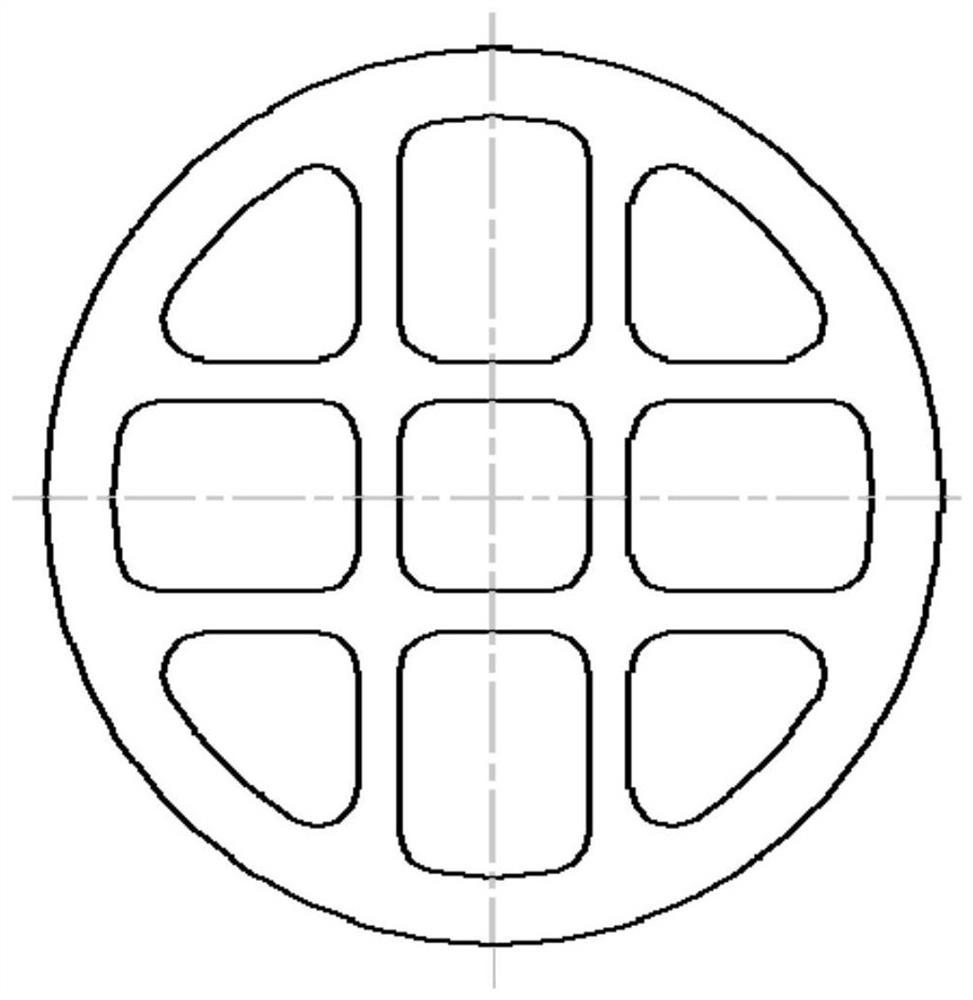
Figure 3
Abstract
Description
technical field
[0001] The invention relates to a high-efficiency and complete management device for propellant in a surface tension storage tank, which belongs to the field of space propulsion technology, in particular to a management device for propellant in a satellite propulsion system. Background technique
[0002] At present, the efficient management technology of satellite propellants in orbit is still one of the hotspots in space propulsion research. Utilizing the principle of liquid driven by surface tension under microgravity, the net-type full-management technology that realizes the storage of gas-free liquid in the management device is the preferred technology for satellites with strong mobility and high acceleration. Mesh surface tension tank is the earliest surface tension tank used in orbit, and its use is a revolution in the development of satellite propellant tanks. Compared with conical storage tanks and diaphragm storage tanks, it has excellent performanc...
Examples
Embodiment
[0055] Such as Figure 1-4 As shown, a high-efficiency full management device for propellant in a surface tension storage tank, including: four axial pipelines 2, deflation pipeline 4, annular pipeline 5, cross support frame 6 and liquid reservoir 8; The pipelines 2 are respectively marked as the first axial pipeline, the second axial pipeline, the third axial pipeline and the fourth axial pipeline; the cross support frame 6 has four ends, and the four ends marked as a first end, a second end, a third end and a fourth end, respectively;
[0056] The circumferential pipeline 5 is a ring, and the axial pipeline 2 is a C-shaped structure;
[0057] Each axial pipeline 2 has two axial accumulators 3 distributed symmetrically on the plane where the circumferential pipeline 5 is located;
[0058] There are eight evenly distributed annular accumulators 7 on the annular pipeline 5;
[0059] The right side of the liquid reservoir 8 has a liquid outlet 9, the liquid outlet 9 is used f...