
Electric mechanical stretching device
A stretching device and mechanical technology, applied in the field of furniture, can solve the problems of reduced comfort, complex running track, complicated use process, etc., and achieve the effect of reducing force transmission process, simple movement track, and simple use process.
Patent Information
- Authority / Receiving Office
- CN · China
- Patent Type
- Applications(China)
- Current Assignee / Owner
- Publication Date
- 2020-01-17
- Estimated Expiration
- Not applicable · inactive patent
Smart Images
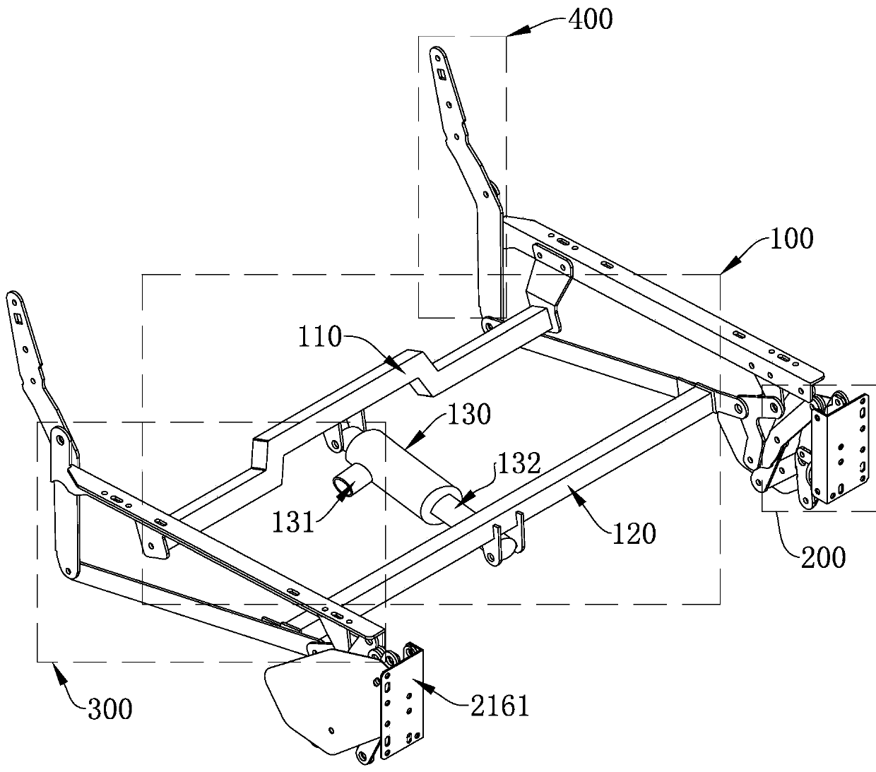
Figure 1 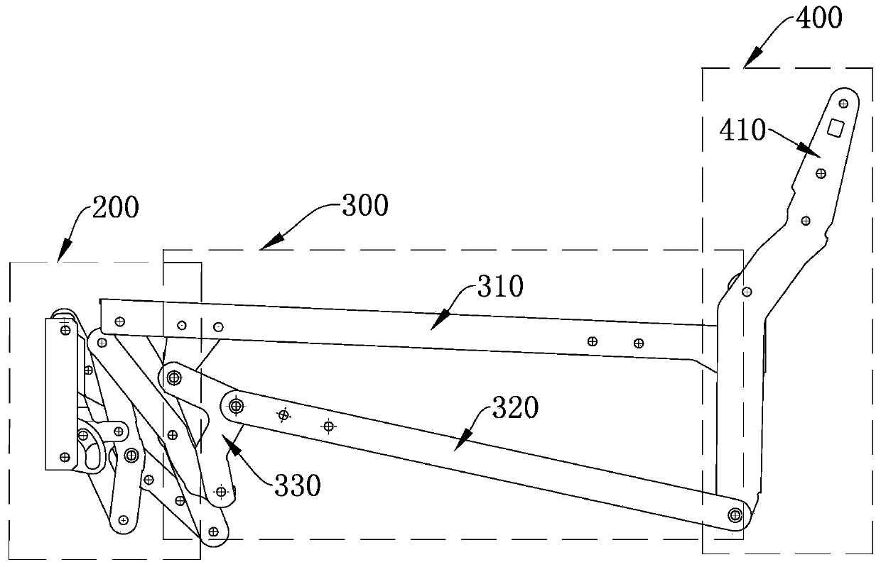
Figure 2 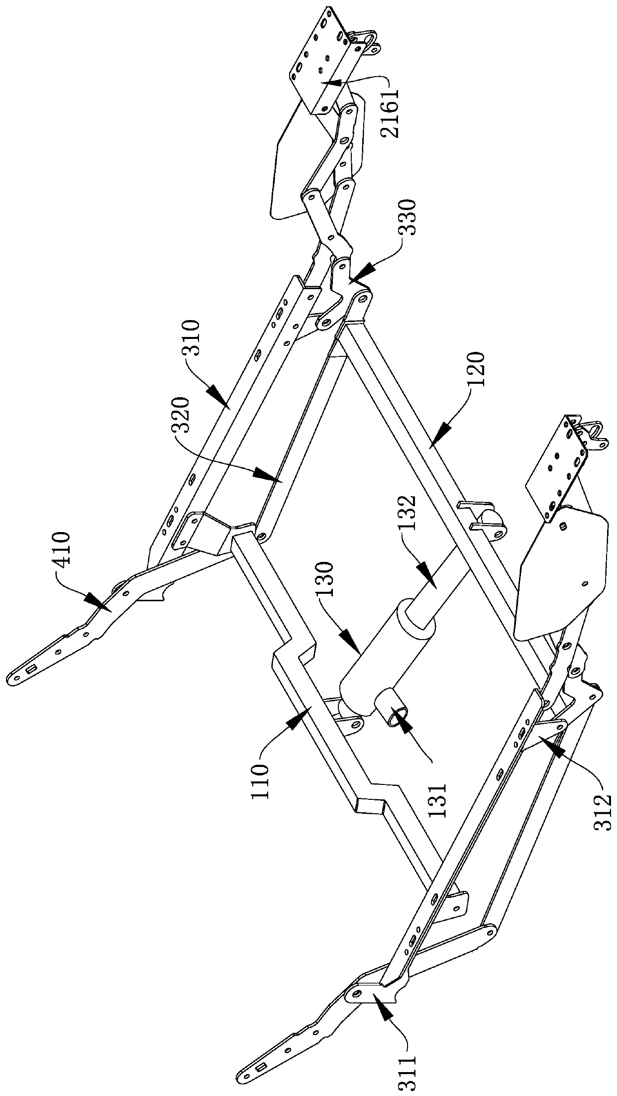
Figure 3
Abstract
Description
technical field
[0001] The invention relates to the technical field of furniture, in particular to an electromechanical stretching device. Background technique
[0002] The electromechanical stretching device is a functional frame product that is widely used in functional sofa seats at present. Users can adjust the different states of the sofa seat according to their own needs (such as sitting and lying positions), which is comfortable and convenient; however, the existing electromechanical stretching device The device is generally complex in structure, bulky and bulky, resulting in limited functional design and waste of space in seat design, and there are many problems such as complicated use process, low fit, poor comfort, inconvenient transportation, and high cost; specifically, In other words, for example, complex and numerous rods are easy to interfere and limit the design of the seat frame’s low position and seat frame lengthening; for another example, the complex stru...
Examples
specific Embodiment approach
[0034] The directional words such as "front" and "rear" involved in this embodiment are described by the user's field of view after the user sits on the seat. For example, the front of the user is "front", and the legrest assembly 200 , the seat frame support assembly 300 and the backrest assembly 400 are arranged sequentially from front to back.
Embodiment
[0036] An electromechanical stretching device such as Figure 1~4 As shown, the drive assembly 100 is included, and the left and right sides of the drive assembly 100 are provided with left and right paired leg rest assemblies 200, seat frame support assemblies 300 and backrest assemblies 400, and the front and rear ends of the seat frame support assembly 300 are respectively connected to the leg rest assemblies. One end of assembly 200 is hinged to one end of backrest assembly 400 .
[0037] Specifically, the seat frame support assembly 300 includes a support fixed rod 310 and a support transmission rod 320 distributed up and down, the rear end of the support fixed rod 310 and the rear end of the support transmission rod 320 are hinged with the backrest assembly 400, supporting The front end of the fixed rod 310 is hinged with the leg rest assembly 200, and the front end of the supporting transmission rod 320 is hinged with a linkage rod 330, the linkage rod 330 is a crank stru...