
Automatic tubular material feeding conveying equipment
A technology for conveying equipment and materials, which is applied in the field of automatic upper tubular material conveying equipment, can solve the problems of low packaging efficiency of single parts, increased labor intensity, and prolonged packaging time, so as to save labor costs, improve production efficiency, and reduce manufacturing costs. Effect
Patent Information
- Authority / Receiving Office
- CN · China
- Patent Type
- Applications(China)
- Current Assignee / Owner
- Publication Date
- 2020-01-24
Smart Images
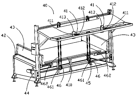
Figure 1 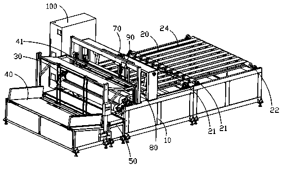
Figure 2 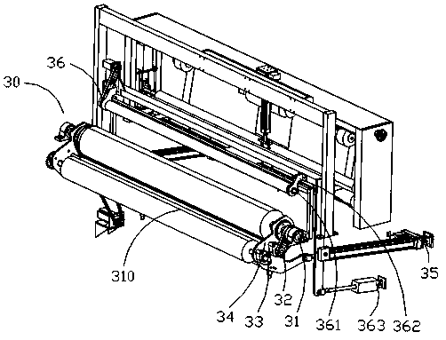
Figure 3
Abstract
Description
technical field
[0001] The invention relates to an automatic upper tubular material conveying device, which belongs to the field of material conveying devices. Background technique
[0002] The winding mechanism of the existing winding device adopts a simple double-roller drive with the same diameter and generally arranged in parallel or a three-roller drive with a simple triangular arrangement of the axis. The double-roller drive rollers are placed horizontally or vertically. ; The three-roller transmission adopts two horizontal rollers, and the third roller is placed above the middle of the two horizontal rollers to form an isosceles or equilateral triangle.
[0003] The existing winding device can only use manual plus equipment, semi-automatic or purely manual winding, and the packaging efficiency of a single part is low. It is necessary to pre-cut the material that needs to be rolled into a certain size, and then use manual and semi-automatic or purely manual winding me...
Examples
Embodiment Construction
[0026] Such as Figure 1-2 As shown, an embodiment of the present invention discloses an automatic winding device, comprising: a frame 10, a conveying mechanism 20 arranged on the frame 10, a multi-axis linkage winding mechanism 30, and an automatic upper tubular material conveying device 40, wherein, the automatic upper tubular material conveying equipment 40 includes a discharge push rod mechanism 41, and the discharge push rod mechanism 41 can move to release the tubular material 410 to the preset position of the multi-axis linkage winding mechanism 30, the The conveying mechanism 20 is used to convey the tubular material 410 to the multi-axis linkage winding mechanism 30 . Preferably, the frame 10 is cut and welded from a 40x80mm, 50x100mm, 60*120mm square tube or a 1-20mm plate. The above-mentioned automatic loading tubular material conveying device 40 can work alone or in combination with the above-mentioned automatic winding device, and can also be applied to other occ...