
Relay armature deformer
A deformer and relay technology, applied in relays, circuits, electrical components, etc., can solve problems such as poor deformation effect, inability to locate, and generation of foreign objects, so as to avoid repeated deformation, improve production efficiency, and produce no foreign objects and noise Effect
Patent Information
- Authority / Receiving Office
- CN · China
- Patent Type
- Applications(China)
- Current Assignee / Owner
- Publication Date
- 2020-07-24
Smart Images
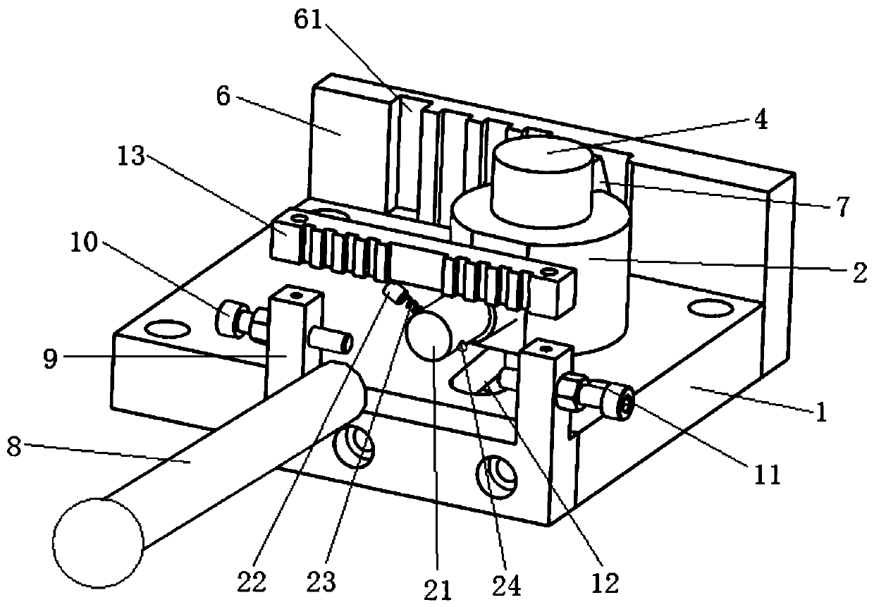
Figure 1 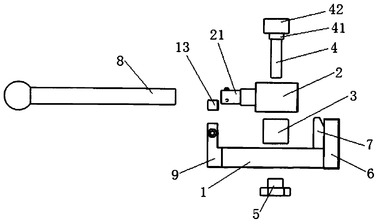
Figure 2 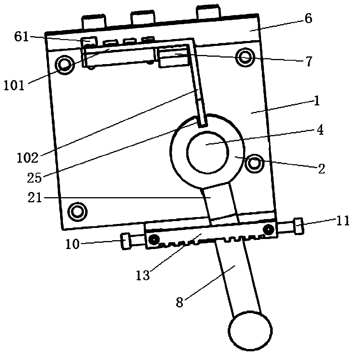
Figure 3
Abstract
Description
technical field
[0001] The invention belongs to the technical field of armature deformers, and relates to a relay armature deformer. Background technique
[0002] When adjusting the relay, it is necessary to complete the adjustment of the electrical characteristics of the relay by changing the angle of the armature. Over the years, the workshop has adopted various methods to change the angle of the armature, all of which are not ideal. When changing the angle of the armature, it cannot be positioned, and sometimes the angle of the armature is repeatedly changed, and various scum is generated in the process. This production form It affects production efficiency and product quality, and is not suitable for dust-free production in the workshop. SUMMARY OF THE INVENTION
[0003] The purpose of the present invention is to provide a relay armature deformer, which solves the problems of inability to locate the armature during deformation, poor deformation effect, generation of f...
Examples
Embodiment Construction
[0014] like Figures 1 to 3 As shown, a relay armature deformer of the present invention includes: a base 1, a rotary deformer 2, a positioning bushing 3, a positioning nail 4, a guide locking nail 5, a first limit plate 6, and a second limit plate 7. Rod 8, angle limiter 9, left limit pin 10 and right limit pin 11.
[0015] The positioning shaft sleeve 3 is a cylindrical structure, the rotary deformer 2 is sleeved on the outside of the positioning shaft sleeve 3, the base 1 is provided with a sliding slot 12, the positioning nail 4 and the guide locking nail 5 Respectively extend from the upper and lower sides of the sliding slot 12 into the positioning bushing 3 to lock the positioning bushing 3 on the base 1 by screwing. The screw heads are embedded in the steps to ensure the flatness of the bottom surface of the base 1. The first limit plate 6 is fixed on one side of the base 1 , the second limit plate 7 is riveted to the base 1 , a mounting groove is formed between the ...