
Worm gear deviation correcting device
The technology of a deviation rectifying device and a worm gear is applied in the field of deviation adjusters, which can solve the problem that the deviation adjuster cannot effectively rectify the deviation of the conveyor belt, and achieve the effects of stable overall performance, long service life and smooth movement.
Patent Information
- Authority / Receiving Office
- CN · China
- Patent Type
- Applications(China)
- Current Assignee / Owner
- Publication Date
- 2020-08-04
Smart Images
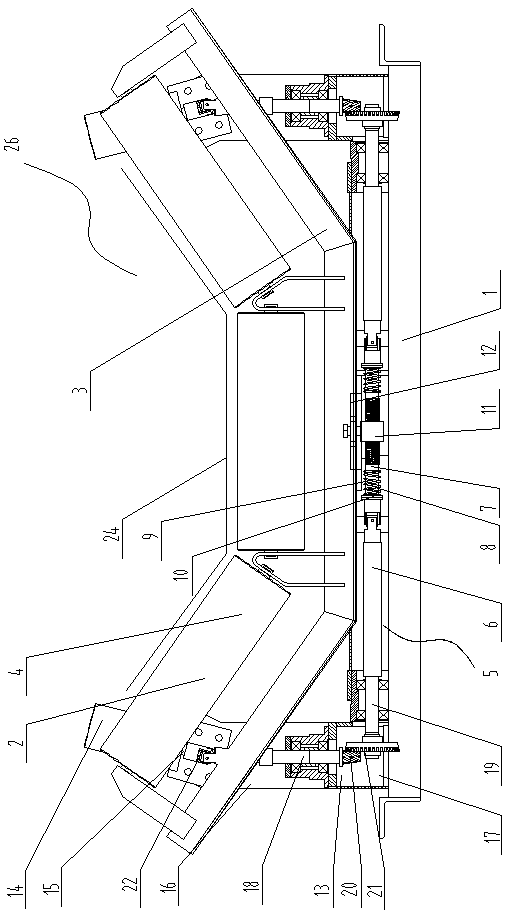
Figure 1 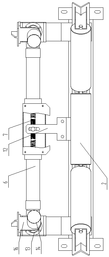
Figure 2 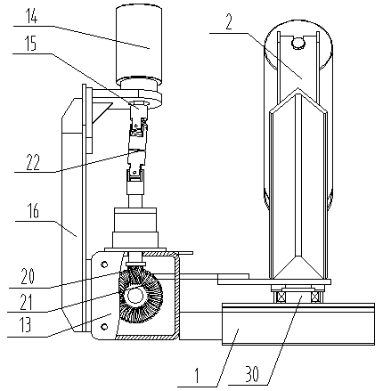
Figure 3
Abstract
Description
technical field
[0001] The invention relates to a deviation adjuster, in particular to a deviation correcting device for a worm gear. Background technique
[0002] Conveyor belt conveyor is a kind of material transportation equipment. There are driving rollers and reversing rollers at both ends of the endless conveyor belt. There are multiple idler groups under the conveyor belt to support the conveyor belt. When working, the material is placed on the conveyor belt. The rotation of the driving drum drives the conveyor belt to make directional movement, so as to transport the material to the desired location.
[0003] Because the conveyor belt is running under load, it often happens that the conveyor belt deviates due to uneven force, incorrect center point, and incorrect blanking point. The current method of correcting deviation: ① Weld a set of force arm rods at both ends of the bracket of the self-aligning idler group, and fix the vertical retaining roller on the force ar...
Examples
Embodiment Construction
[0023] Such as Figure 1-3 As shown, the present invention discloses a worm gear and worm deviation correcting device 26, including a frame 1, on which an idler assembly 2 is arranged, on which an idler assembly 2 supports a conveyor belt 24, and the idler assembly 2 includes an idler bracket 3 and rotate the idler roller 4 mounted on the idler bracket 3, the center of the bottom of the idler assembly 2 is installed on the frame 1 through the bracket rotation shaft 5 through the belt seat bearing 30, and the idler assembly 2 is on one side along the conveying direction A transmission rod 5 is provided, and the transmission rod 5 is parallel to the width direction of the frame 1. The transmission rod 5 includes two transitional connecting rods 6 and a screw section 7 connected between the two transitional connecting rods 6. Both ends are polished rod sections 9, and springs 8 are respectively inserted on the polished rod sections 9, and spring limit retaining rings 10 are respe...