
A desulfurization and denitrification system based on electrolysis of seawater and its process
A desulfurization and denitrification, seawater technology, applied in the field of desulfurization and denitrification systems, can solve the problems of difficulty in providing installation space and conditions, difficulty in improving desulfurization and denitrification efficiency, and low spray density and intensity, so as to reduce system energy consumption and improve space utilization. good thermal conductivity and thermal conductivity
Patent Information
- Authority / Receiving Office
- CN · China
- Patent Type
- Patents(China)
- Current Assignee / Owner
- Publication Date
- 2022-03-08
Smart Images
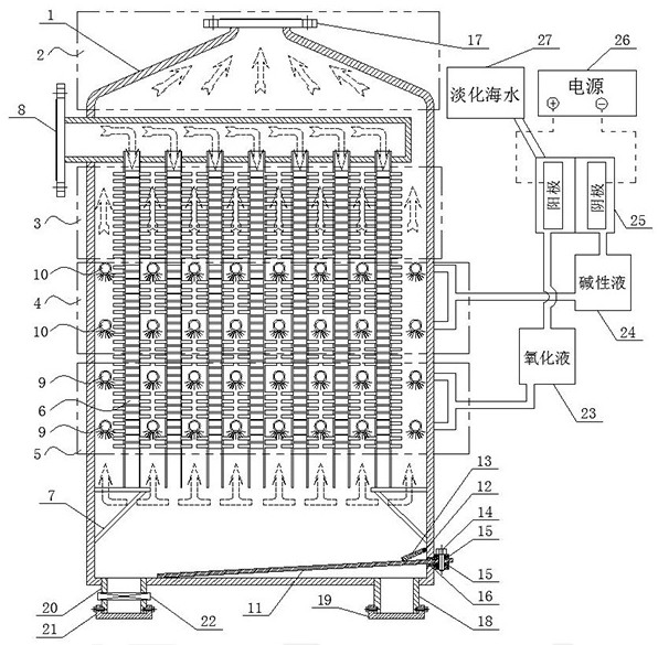
Figure 1 
Figure 2 
Figure 3
Abstract
Description
technical field
[0001] The invention relates to the technical field of waste gas treatment, in particular to a desulfurization and denitrification system based on electrolysis of seawater and a process thereof. Background technique
[0002] According to statistics, on a global scale, the air pollution caused by exhaust emissions from marine diesel engines accounts for about 5-10% of the total air pollution, and even as high as 30-40% in port cities; with the continuous growth of global shipping volume, this Undoubtedly, the proportion of environmental pollution in coastal cities will be significantly increased; so far, the improvement speed of ship environmental protection measures has not kept pace with the speed of increase in shipping volume; therefore, how to effectively control the exhaust emissions in the process of ship transportation has become the focus of attention of all countries .
[0003] In order to strengthen the protection of the marine ecological environme...
Examples
Embodiment Construction
[0036] The technical solutions of the present invention will be clearly and completely described below through specific embodiments.
[0037] A desulfurization and denitrification system based on electrolytic seawater of the present invention includes a tower body 1, a flue gas pipeline 8, a needle-shaped plate device 6, a first spray layer and a second spray layer; the specific structure is as follows figure 1 As shown, a flue gas outlet 17 is connected to the middle position of the top of the tower body 1, and a drain pipe 20 is vertically connected to the bottom side of the tower body 1; Cover 21, the second sealing cover 21 is matched with the discharge pipe 20, and the two are sealed and screwed together; a solenoid valve 22 is also socketed and fixed on the discharge pipe 20, and the solenoid valve 22 is located on the second sealing Between the cover 21 and the bottom of the tower body 1, it is used to control the discharge of waste liquid.
[0038] In the present inve...