
Foaming machine
A technology of foaming machine and driving mechanism, which is applied in mixers, mixers with rotating containers, mixing methods, etc. It can solve the problems of single stirring form, swirl and stratification of raw materials, etc., and achieve high stirring efficiency and high foaming speed. Fast, avoid swirl and layered effects
Patent Information
- Authority / Receiving Office
- CN · China
- Current Assignee / Owner
- Publication Date
- 2020-12-08
- Estimated Expiration
- Not applicable · inactive patent
Smart Images
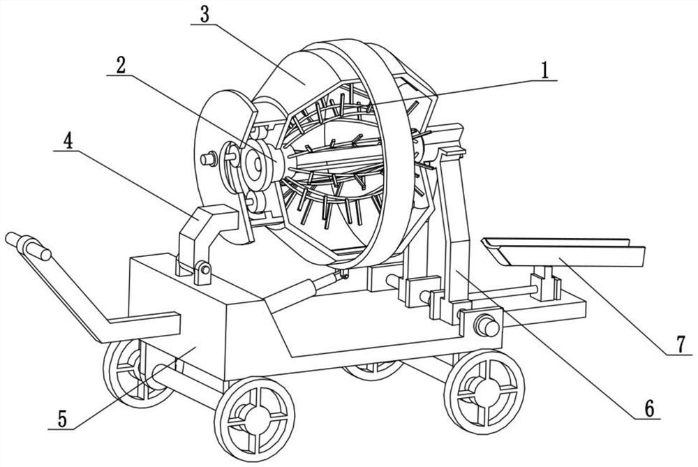
Figure 1 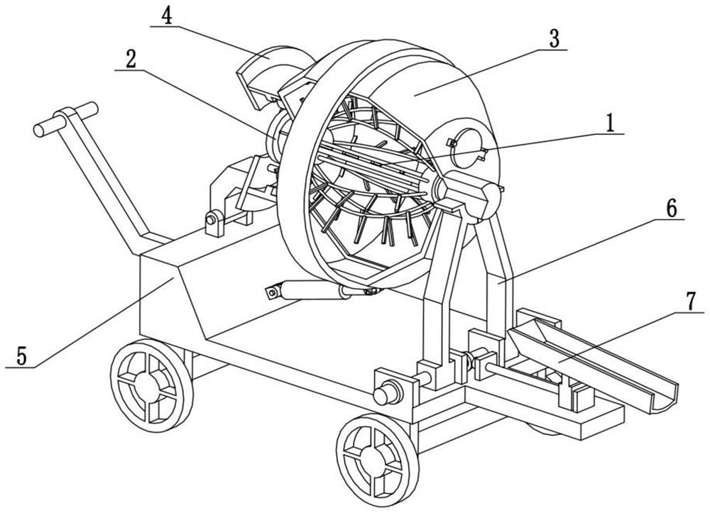
Figure 2 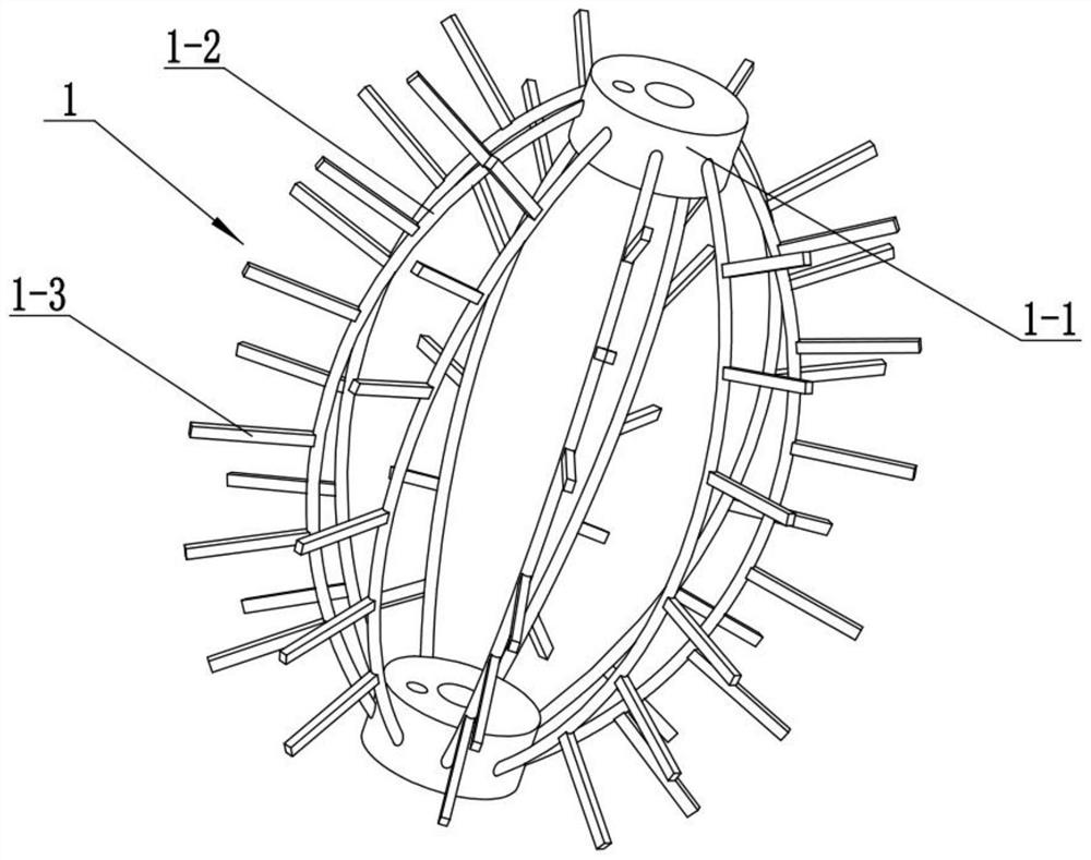
Figure 3
Abstract
Description
technical field
[0001] The invention relates to the technical field of foaming machines, more specifically to a foaming machine. Background technique
[0002] The invention with the publication number CN108579597A discloses a foaming machine capable of ensuring a constant discharge temperature, including a foaming machine body. Air inlet pipes and auxiliary agent addition pipes are respectively installed on the left and right sides of the top of the foaming machine body. A motor is installed on the left side of the feed box, and a rotating shaft is installed at the power output end on the right side of the motor. The outer wall of the rotating shaft is provided with a spiral stirring blade, and a filter screen is installed horizontally in the inner cavity of the feed box. A temperature sensor is installed on the top of the right side of the inner cavity of the foaming machine body, and a heating coil is wound on the inner wall of the foaming machine body. Through spiral stir...
Examples
specific Embodiment approach 1
[0027] Combine below Figure 1-10 Describe this embodiment, the present invention relates to the field of foaming machine technology, more specifically, a foaming machine, including an elastic adjustment foaming mechanism 1, an adjustment drive mechanism 2, a foaming rotating tank mechanism 3, and a rotating power mechanism 4 , the loading and unloading rotating mechanism 5, the tank supporting mechanism 6 and the discharge guiding mechanism 7, the tank supporting mechanism 6 is fixedly connected to the loading and unloading rotating mechanism 5, and the discharging guiding mechanism 7 is fixedly connected to the right end of the loading and unloading rotating mechanism 5 , the tank supporting mechanism 6 and the tank supporting mechanism 6 are meshed for transmission, the rotating power mechanism 4 is rotatably connected to the loading and unloading rotating mechanism 5, the foaming rotating tank mechanism 3 is rotatably connected to the rotating power mechanism 4, and the adj...
specific Embodiment approach 2
[0030] Combine below Figure 1-10 Describe this embodiment, this embodiment will further explain the first embodiment, the elastic adjustment and foaming mechanism 1 includes an opening and closing adjustment bushing 1-1, an arc-shaped elastic connecting rod 1-2 and a foaming stirring rod 1-3 , there are two opening and closing adjustment bushings 1-1, and a plurality of arc-shaped elastic connecting rods 1-2 are arranged between the two opening-closing adjusting bushings 1-1, and a plurality of arc-shaped elastic connecting rods 1-2 All are provided with a plurality of foaming stirring rods 1-3.
[0031] When the two opening and closing adjustment bushings 1-1 are close to each other, the two opening and closing adjustment bushings 1-1 will squeeze a plurality of arc-shaped elastic connecting rods 1-2, so that the plurality of arc-shaped elastic connecting rods 1-2 Bending occurs, and at the same time, multiple arc-shaped elastic connecting rods 1-2 drive multiple foaming st...
specific Embodiment approach 3
[0033] Combine below Figure 1-10 Describe this embodiment, this embodiment will further explain the second embodiment, the adjustment drive mechanism 2 includes a follow-up rotating cylinder 2-1, a connecting plate 2-2, a rotating screw rod 2-3, and a limit slide rod 2 -4, adjust the motor 2-5 and the ring rack 2-6, the ring rack 2-6 is fixedly connected to the left end of the follow-up rotating cylinder 2-1, and the rotating screw mandrel 2-3 is connected to the follow-up rotating cylinder 2-1 in rotation And on the connecting plate 2-2, the rotating screw mandrel 2-3 is fixedly connected on the output shaft of the adjustment motor 2-5, the adjustment motor 2-5 is fixedly connected in the follow-up rotating cylinder 2-1, and the limit slide bar 2- 4. It is fixedly connected to the follow-up rotating cylinder 2-1 and the connecting plate 2-2. The two opening and closing adjustment bushings 1-1 are connected to the left and right sides of the rotating screw rod 2-3 through thr...