
Pressure sensor protection device capable of eliminating impact force
A pressure sensor and protection device technology, applied in the field of sensors, can solve the problems of easily damaged sensors and measurement errors, and achieve the effect of simple device structure, convenient operation, and avoiding direct damage
Patent Information
- Authority / Receiving Office
- CN · China
- Patent Type
- Applications(China)
- Current Assignee / Owner
- Publication Date
- 2020-12-22
- Estimated Expiration
- Not applicable · inactive patent
Smart Images
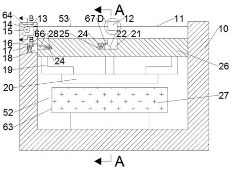
Figure 1 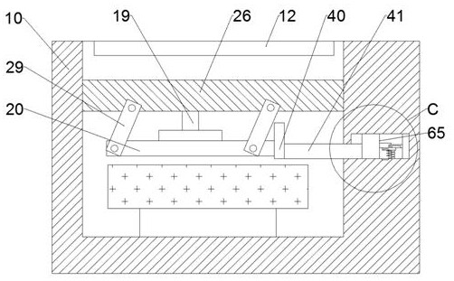
Figure 2 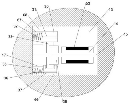
Figure 3
Abstract
Description
technical field
[0001] The invention relates to the field of sensors, in particular to a pressure sensor protection device capable of eliminating impact force. Background technique
[0002] Sensors are currently widely used in various fields. In machinery, sensors are equivalent to mechanical perception systems. They can control the movement of machinery by sensing changes in various physical quantities. Pressure sensors are used to convert the physical quantity of pressure into a mechanical movement that can be controlled. device.
[0003] At this stage, many pressure sensors are used to measure the gravity of objects. When measuring the gravity of objects, the general pressure sensors need to be placed lightly before measurement. They are generally used for experimental measurement operations. Large error, and very easy to damage the sensor. Contents of the invention
[0004] The technical problem to be solved by the present invention is to provide a pressure sensor pr...
Examples
Embodiment Construction
[0018] Combine below Figure 1-6 The present invention is described in detail, wherein, for the convenience of description, the orientations mentioned below are defined as follows: figure 1 The up, down, left, right, front and back directions of the projection relationship itself are the same.
[0019] combined with Figure 1-6 A pressure sensor protection device capable of eliminating impact force, comprising a buffer seat 10, the upper end of the buffer seat 10 is provided with a measurement cavity 52 with an upward opening, the left side of the upper end is provided with a buffer cavity 13, and the rear of the measurement cavity 52 is A pushing chamber 50 with an opening forward is also provided on the wall of the chamber, a measuring mechanism 63 is arranged in the measuring chamber 52, a buffer mechanism 64 is arranged in the buffer chamber 13, a supporting mechanism 65 is arranged in the pushing chamber 50, The measuring mechanism 63 includes a right buffer net 11 fixe...