
Energy-saving type injection molding equipment used for double-sided injection molding and capable of preventing raw materials from overflowing
An injection molding equipment and energy-saving technology, applied in the field of energy-saving injection molding equipment, can solve the problems of incomplete product molding, insufficient injection speed, insufficient mold material, etc., and achieve the effects of reducing production volume, preventing backflow, and saving materials
Patent Information
- Authority / Receiving Office
- CN · China
- Patent Type
- Applications(China)
- Current Assignee / Owner
- Publication Date
- 2021-02-02
- Estimated Expiration
- Not applicable · inactive patent
Smart Images
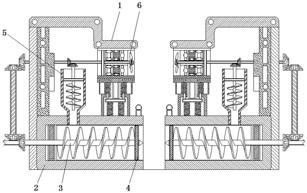
Figure 1 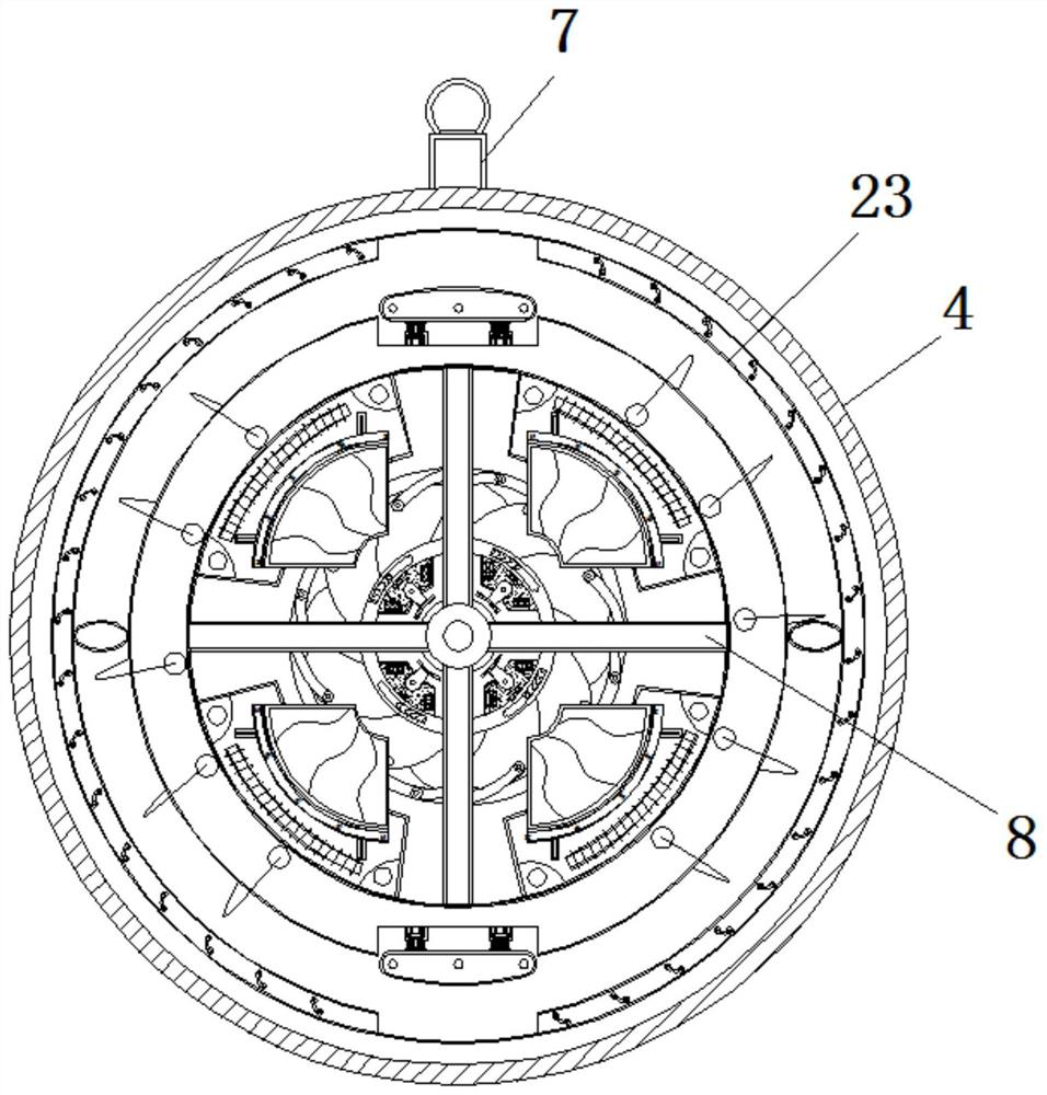
Figure 2 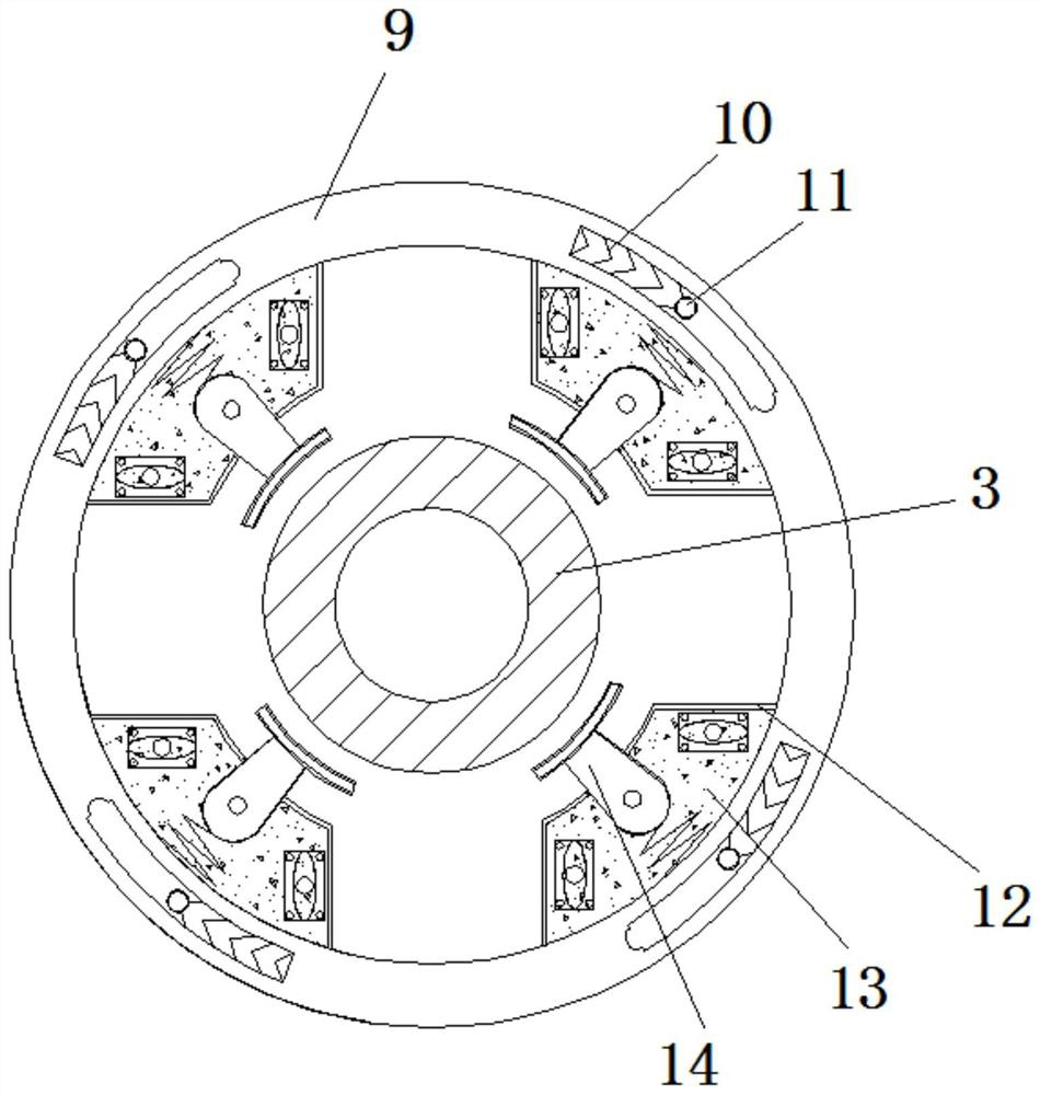
Figure 3
Abstract
Description
technical field
[0001] The invention relates to the technical field of plastic injection molding equipment, in particular to an energy-saving injection molding equipment used for double-sided injection molding to prevent overflow of raw materials. Background technique
[0002] Injection molding is a method of producing shapes for industrial products. Products usually use rubber injection molding and plastic injection molding. Injection molding can also be divided into injection molding molding method and die-casting method. At present, the injection devices of general injection machines on the market adopt the method of direct feeding.
[0003] However, in the process of feeding the existing equipment, the residual material in the injection tube will flow out through the injection port, resulting in waste of material. In addition, the injection speed is insufficient, and the material inside the mold is not enough, which easily leads to poor molding of the product. Complete...
Examples
Embodiment Construction
[0022] The following will clearly and completely describe the technical solutions in the embodiments of the present invention with reference to the accompanying drawings in the embodiments of the present invention. Obviously, the described embodiments are only some, not all, embodiments of the present invention. Based on the embodiments of the present invention, all other embodiments obtained by persons of ordinary skill in the art without making creative efforts belong to the protection scope of the present invention.
[0023] see Figure 1-6 , an energy-saving injection molding equipment used for double-sided injection molding to prevent raw materials from spilling, comprising a main body 1, an injection tube 2 is fixedly connected to the right side of the main body 1, and a screw rod 3 is inserted into the inside of the injection tube 2, and the screw rod The outside of the right end of 3 is sleeved with a fixed plate 4, the upper surface of the injection pipe 2 is plugged ...