
Novel rapid discharging valve applied to large foaming machine
A foaming machine, a new type of technology, applied in the direction of mechanical equipment, fluid pressure actuators, servo motor components, etc., can solve the problem of affecting the working efficiency of the hydraulic system of the large foaming machine, the slow pressure relief speed, and the impact of the large foaming machine Foaming quality and other issues, to achieve the effect of novel structure, fast pressure relief, and strong practicability
Patent Information
- Authority / Receiving Office
- CN · China
- Patent Type
- Applications(China)
- Current Assignee / Owner
- Publication Date
- 2021-03-12
Smart Images
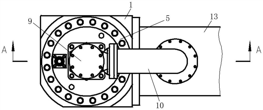
Figure 1 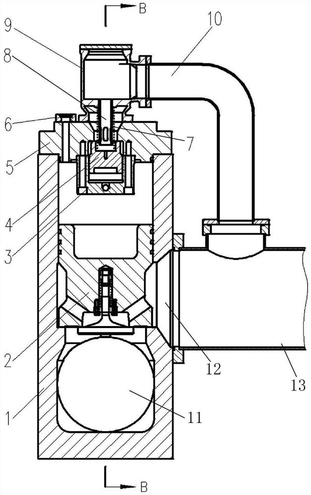
Figure 2 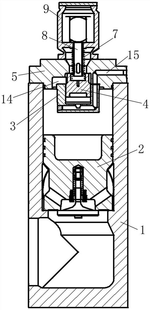
Figure 3
Abstract
Description
technical field
[0001] The invention belongs to the field of large foaming machine accessories, in particular to an EVA foaming machine, and relates to a novel quick-discharging valve applied in a large foaming machine. Background technique
[0002] The quick discharge valve in the existing large foaming machine will have the problem of slow pressure relief, which will not only affect the working efficiency of the hydraulic system of the large foaming machine, but also affect the foaming quality of the large foaming machine . Contents of the invention
[0003] In order to solve the above problems, the present invention provides a new type of quick discharge valve applied in large foaming machines. The present invention has the characteristics of novel structure, faster pressure relief speed and stronger practicability.
[0004] In order to achieve the above object, the present invention adopts the following specific technical measures: a new type of quick discharge valve ...
Examples
Embodiment Construction
[0033] Such as figure 1 , figure 2 , image 3 , Figure 4 As shown, a new type of quick discharge valve used in a large foaming machine is composed of a vertical main valve body 1, a main piston mechanism 2, a pilot valve body 3, a pilot valve piston 4, a valve cover 5, and a main valve plus The pressure flange 6, the spring, the tee flange 9, the oil return pipe 10, and the vertical core pipe 8 are characterized in that,
[0034] The lower end of the front side of the vertical main valve body 1 is integrally formed with the first oil port 11 connected to the main oil cylinder, the lower end of the right side of the vertical main valve body 1 is integrally formed with the second oil port 12, and a pipe of the horizontal oil pipe 13 One end communicates with the second oil port 12, and the other end of the transverse oil pipe 13 communicates with the oil tank;
[0035] The inside of the vertical main valve body 1 is integrally formed with a vertical oil chamber, the first ...