
Optical lens and imaging equipment
A technology of optical lens and imaging surface, which is applied in the field of imaging lens, can solve the problems of large size, achieve the balance of high pixels, achieve miniaturization, and improve the effect of camera experience
Patent Information
- Authority / Receiving Office
- CN · China
- Patent Type
- Patents(China)
- Current Assignee / Owner
- Publication Date
- 2021-05-14
Smart Images
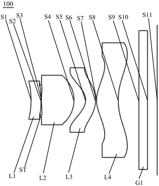
Figure 1 
Figure 2 
Figure 3
Abstract
Description
technical field
[0001] The present invention relates to the technical field of imaging lenses, in particular to an optical lens and an imaging device. Background technique
[0002] The optical lens is an important part of the optical imaging system, and it is one of the standard configurations of mobile phones, tablets, security monitoring equipment, driving recorders and other terminals. In recent years, with the continuous development of mobile information technology, the demand for terminals has continued to increase, and the number of lenses mounted on terminals has also increased.
[0003] With the enthusiasm of users for thin and light terminals, and in pursuit of better imaging effects, optical lenses are required to meet both miniaturization and wide viewing angles. However, in the prior art, the optical lenses currently on the market cannot A better balance between miniaturization and wide viewing angle leads to the sacrifice of viewing angle when miniaturizing the...
Examples
no. 1 example
[0087] see figure 1 , an optical lens 100 provided by the first embodiment of the present invention includes sequentially from the object side to the imaging surface: a first lens L1, a diaphragm ST, a second lens L2, a third lens L3, a fourth lens L4 and a filter slice G1, where:
[0088] The first lens L1 has negative refractive power, the object side S1 of the first lens is concave, and the image side S2 of the first lens is convex;
[0089] The second lens L2 has positive refractive power, the object side S3 of the second lens is convex at the near optical axis, and the image side S4 of the second lens is convex;
[0090] The third lens L3 has negative refractive power, the object side S5 of the third lens is concave at the near optical axis, and the image side S6 of the third lens is convex;
[0091] The fourth lens L4 has positive refractive power, the object side S7 of the fourth lens is convex at the near optical axis, the image side S8 of the fourth lens is concave ...
no. 2 example
[0103] see Figure 5 , which is a schematic structural diagram of the optical lens 200 provided by the second embodiment of the present invention. The optical lens 200 provided by the second embodiment of the present invention has substantially the same structure as the optical lens 100 provided by the first embodiment, and the difference is mainly in that : the first lens L1 has positive refractive power, and its object side S1 is convex at the near optical axis; the second lens L2 has positive refractive power, and its object side S3 is concave at the near optical axis; and the radius of curvature of each lens, Material choices vary. In the second embodiment of the present invention, the vertical distance between the inflection point on the object side surface S7 of the fourth lens and the optical axis is 0.855 mm.
[0104] Please refer to Table 3, which shows the relevant parameters of each lens in the optical lens 200 provided by the second embodiment of the present inven...
no. 3 example
[0115] see Figure 9 , which is a schematic structural diagram of the optical lens 300 provided by the third embodiment of the present invention. The optical lens 300 provided by the third embodiment of the present invention has substantially the same structure as the optical lens 100 provided by the first embodiment, and the difference is mainly in that : the first lens L1 has positive refractive power, and its object side S1 is convex at the near optical axis; the second lens L2 has positive refractive power, and its object side S3 is concave at the near optical axis; and the radius of curvature of each lens, Material choices vary. In the third embodiment of the present invention, the vertical distance between the inflection point on the object side S7 of the fourth lens and the optical axis is 0.836 mm.
[0116] Please refer to Table 5, which shows the relevant parameters of each lens in the optical lens 300 provided by the third embodiment of the present invention.
[01...