
Optical Lenses and Imaging Equipment
A technology of optical lens and imaging surface, which is applied in optics, optical components, instruments, etc., can solve the problems of unfavorable popularization and application, high production cost, and large volume, and achieve the effects of cost reduction, simple processing, and light weight
Patent Information
- Authority / Receiving Office
- CN · China
- Patent Type
- Patents(China)
- Current Assignee / Owner
- Publication Date
- 2021-01-01
Smart Images
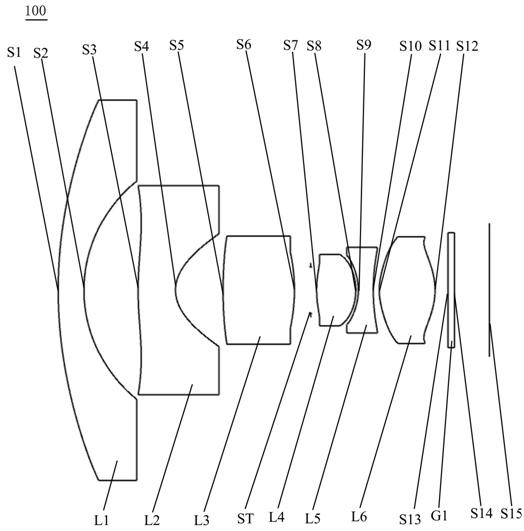
Figure 1 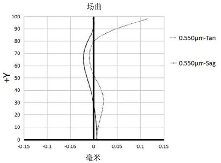
Figure 2 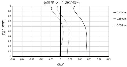
Figure 3
Abstract
Description
technical field
[0001] The invention relates to the technical field of lens imaging, in particular to an optical lens and an imaging device. Background technique
[0002] Fisheye lens is an optical imaging system with super large field of view and large aperture, which is widely used in measurement fields such as panoramic monitoring, satellite positioning, robot navigation, and micro intelligent systems. With the rise of VR technology and panoramic photography, the consumer electronics market has a very high demand for high-resolution fisheye lenses.
[0003] Fisheye lenses currently on the market are usually composed of all-glass lenses, or glass-plastic hybrid lenses. Such wide-angle fisheye lenses are usually bulky, heavy, and costly to produce, which is not conducive to market promotion and application. Contents of the invention
[0004] Therefore, the object of the present invention is to provide an optical lens and an imaging device for solving the above problems. ...
Examples
no. 1 example
[0060] see figure 1 , which is a schematic structural view of the optical lens 100 provided by the first embodiment of the present invention, the optical lens 100 includes in sequence from the object side to the image side along the optical axis: a first lens L1, a second lens L2, a third lens L3, Stop ST, fourth lens L4, fifth lens L5, sixth lens L6 and filter G1.
[0061] Wherein, the first lens L1 has negative refractive power, the object side S1 of the first lens is convex, and the image side S2 of the first lens is concave. The second lens L2 has negative refractive power, the object side S3 of the second lens is convex at the near optical axis and has at least one inflection point, and the image side S4 of the second lens is concave. The third lens L3 has positive refractive power, the object side S5 of the third lens is convex, and the image side S6 of the third lens is convex. The fourth lens L4 has positive refractive power, the object side S7 of the fourth lens is ...
no. 2 example
[0073] The structure of the optical lens provided by the second embodiment of the present invention is substantially the same as that of the optical lens 100 provided by the first embodiment, except that the radii of curvature of the lenses are different.
[0074] In the second embodiment of the present invention, the vertical distance between the inflection point of the object side S3 of the second lens and the optical axis is 3.25 mm, and the sagittal height between the inflection point and the center of the second lens object side is 0.165 mm.
[0075] The relevant parameters of each lens in the optical lens provided by the second embodiment of the present invention are shown in Table 3.
[0076] table 3
[0077]
[0078] The surface coefficients of each aspheric surface of the optical lens in this embodiment are shown in Table 4.
[0079] Table 4
[0080]
[0081] Please refer to Figure 4 , Figure 5 , respectively show the astigmatism curve and the axial chroma...
no. 3 example
[0083] The structure of the optical lens provided by the third embodiment of the present invention is substantially the same as that of the optical lens 100 provided by the first embodiment, except that the radii of curvature of the lenses are different.
[0084] In the third embodiment of the present invention, the vertical distance between the inflection point of the object side S3 of the second lens and the optical axis is 3.15 mm, and the sagittal height between the inflection point and the center of the second lens object side is 0.145 mm.
[0085] The relevant parameters of each lens in the optical lens provided by the third embodiment of the present invention are shown in Table 5.
[0086] table 5
[0087]
[0088] Table 6 shows the surface coefficients of each aspheric surface of the optical lens in this embodiment.
[0089] Table 6
[0090]
[0091] Please refer to Image 6 , Figure 7 , respectively show the astigmatism curve and the axial chromatic aberrat...