
Portable electroencephalogram sleep monitor
A sleep monitoring, portable technology, used in the field of medical devices, can solve the problem of inaccurate test results
Patent Information
- Authority / Receiving Office
- CN · China
- Current Assignee / Owner
- Publication Date
- 2021-05-25
- Estimated Expiration
- Not applicable · inactive patent
Smart Images
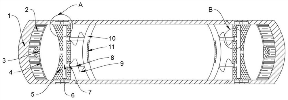
Figure 1 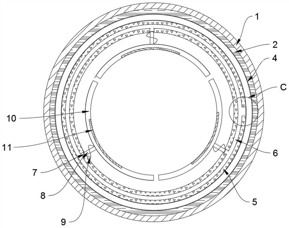
Figure 2 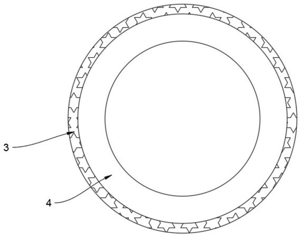
Figure 3
Abstract
Description
technical field
[0001] The invention relates to the technical field of medical devices, in particular to a portable electroencephalogram sleep monitor. Background technique
[0002] The brain waves emitted by the human body in different physiological states have their own characteristics. After more than 100 years of hard work and exploration, medical science has been able to judge the various states of human sleep from the analysis of the brain waves emitted by the human body during sleep. According to the American Academy of Sleep Medicine Sleep and According to the classification of its related event interpretation manual, sleep is divided into: waking period, preparation period, falling asleep period, deep sleep period, and R period. These stages correspond to the waveform and frequency of brain wave signals.
[0003] Different people have different sleep routines, time is also different, and the quality of sleep is also different. The current EEG sleep monitor is genera...
Examples
Embodiment Construction
[0026] The following will clearly and completely describe the technical solutions in the embodiments of the present invention with reference to the accompanying drawings in the embodiments of the present invention. Obviously, the described embodiments are only some, not all, embodiments of the present invention.
[0027] refer to Figure 1-7 , a portable EEG sleep monitor, comprising a housing 1, the inner wall of the housing 1 is fixedly connected with an annular plate 2, the inner wall of the annular plate 2 is provided with an annular chute, and the inner wall of the annular groove is rotatably connected with an annular block 3, The inner side of the annular block 3 is fixedly connected with an annular airbag 4, the side wall of the airbag 4 is fixedly connected with the inner sidewall of the housing 1, and the side of the annular airbag 4 away from the annular block 3 is fixedly connected with an annular clamping plate 5, the top and bottom of the housing 1 Two holes are p...