
Quick propeller mounting mechanism for multi-rotor aircraft
A technology of multi-rotor aircraft and mounting mechanism, which is applied in the direction of rotorcraft, aircraft, unmanned aircraft, etc., can solve the problems of motor output shaft damage, low assembly stability, large volume and weight of fixed base, etc., and achieve reduction The effect of difficulty of operation, reduction of volume and weight, and improvement of convenience
Patent Information
- Authority / Receiving Office
- CN · China
- Patent Type
- Applications(China)
- Current Assignee / Owner
- Publication Date
- 2021-07-13
Smart Images
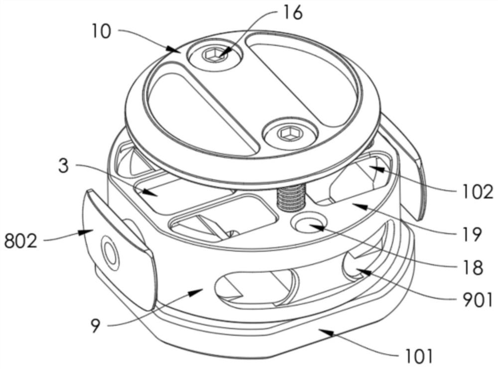
Figure 1 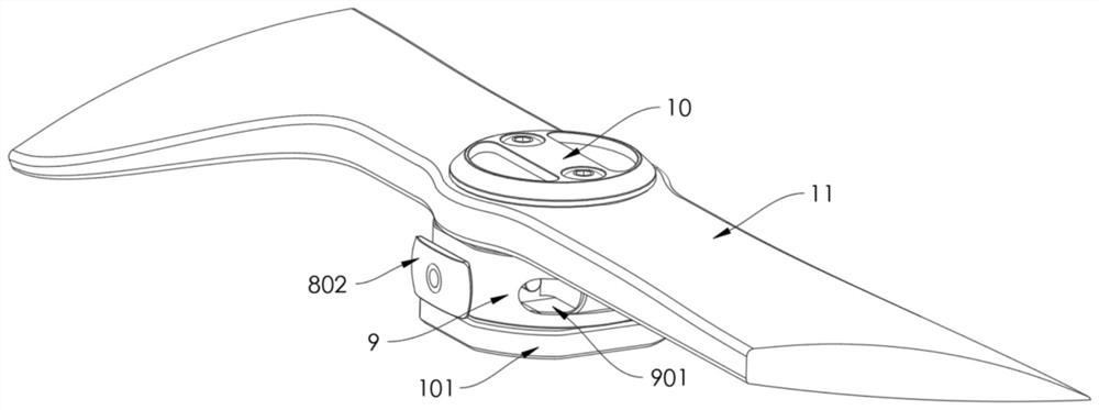
Figure 2 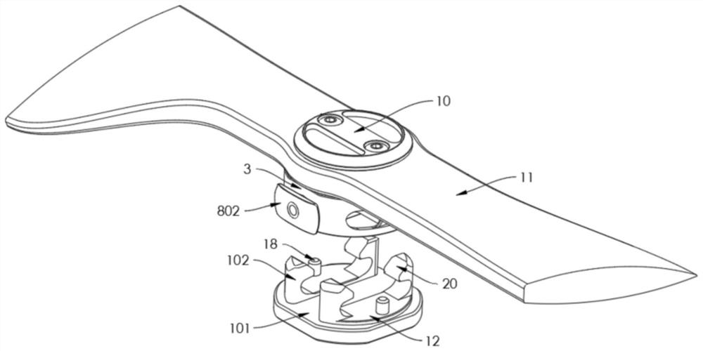
Figure 3
Abstract
Description
technical field
[0001] The invention relates to a quick installation mechanism for a propeller of a multi-rotor aircraft, which is mainly used for quick installation of the propeller for a multi-rotor aircraft. Background technique
[0002] A multi-rotor aircraft refers to a special flight device with three or more rotor shafts, which is equipped with a motor on each shaft to drive the propeller (rotor) through transmission to generate lift. The propellers used in traditional multi-rotor aircraft are generally fixed and locked to the output shaft end of the motor. In order to improve the convenience of use, most of the existing propellers for multi-rotor aircraft adopt a quick installation mechanism, which is detachably connected to the output shaft end of the corresponding motor.
[0003] Existing propeller rapid installation mechanisms for multi-rotor aircraft generally include a fixed base fixed to the output shaft end of the motor and a connector detachably mounted on t...
Examples
Embodiment Construction
[0041] In order to facilitate the understanding of those skilled in the art, the structure of the present invention will be further described in detail with the embodiments in conjunction with the accompanying drawings:
[0042] refer to Figure 1-8 , a fast propeller installation mechanism for a multi-rotor aircraft, comprising
[0043] The fixed base 1 includes a base plate 101 fixedly connected to the output shaft end of the motor and two sets of fasteners 102 arranged on the base plate 101, and the opposite sides of the same set of fasteners 102 are respectively provided with corresponding fastening grooves 2;
[0044] The connecting piece 3 is detachably mounted on the fixed base 1, and the connecting piece 3 is respectively provided with a corresponding chute 4 at a position corresponding to the buckling groove 2, and the connecting piece 3 is mounted on the chute The outer sides of 4 are respectively provided with corresponding mounting holes 5, and corresponding faste...