

Automatic structure for scissor type clamp
An automatic structure and fixture technology, applied in the direction of load hanging components, transportation and packaging, can solve the problems that the fixture cannot be standardized and the scenes are different.
Patent Information
- Authority / Receiving Office
- CN · China
- Patent Type
- Applications(China)
- Current Assignee / Owner
- Publication Date
- 2021-08-06
Smart Images
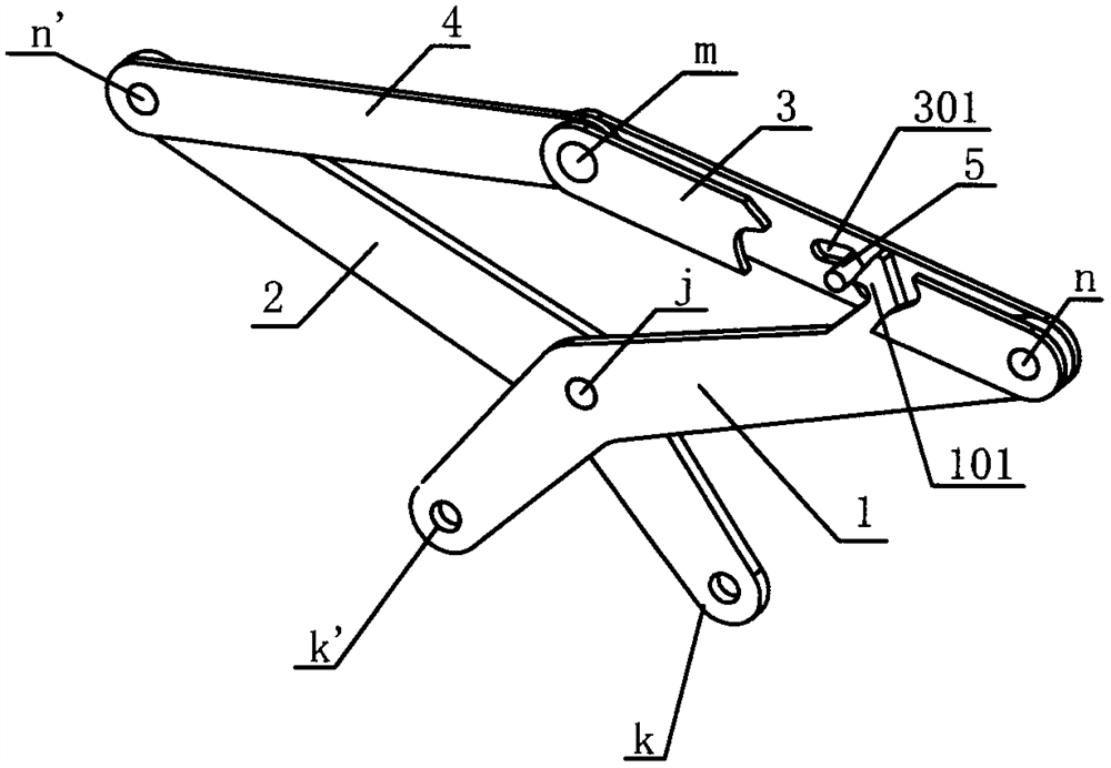
Figure 1 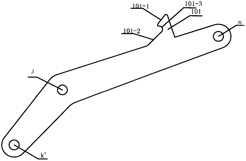
Figure 2 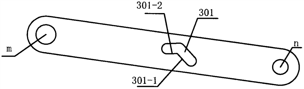
Figure 3
Abstract
Description
technical field
[0001] The invention relates to a lifting fixture, in particular to a fixture with a scissor structure. Background technique
[0002] At present, a large number of scissor fixtures are used to clamp workpieces in industries such as processing, assembly, and logistics at home and abroad. These clamps are generally equipped with a set of devices for controlling the opening and closing of the clamps to improve work efficiency. When operating the fixture, there is no need for personnel to touch or open the fixture, and the automatic opening and closing of the fixture is realized directly by using the self-weight of the fixture and the contact with the upper surface of the workpiece or the ground. The flow sequence during operation is: put down the fixture (to the workpiece) - lift the fixture (fixture clamping) - put down the fixture (to the target area) - lift the fixture (release the fixture). The sequence of "putting-lifting-putting-lifting" can be repeated ...
Examples
Embodiment Construction
[0040] Now in conjunction with embodiment, accompanying drawing, automatic structure of the present invention is described further.
[0041] like figure 1 , Figure 5A kind of automatic structure for scissors fixture shown is characterized in that: comprise scissors arm 1, scissors arm 2, connecting rod 3, connecting rod 4, pin shaft 5, splint 6; Said scissors arm 1 and scissors arm 2 It is hinged at "j"; the upper end of scissors arm 1 is hinged at "n" with (two) connecting rods 3; the upper end of scissors arm 2 is hinged at "n'" with connecting rod 4; connecting rod 3, connecting rod 4 Hinged to each other at "m"; the two connecting rods 3 are respectively arranged on both sides of the connecting rod 4 and the scissor arm 1; there is a chute 301 on the connecting rod 3; the chute 301 is designed in an "L" shape The pin shaft 5 is limited in the chute 301 and can only roll in the chute 301; the scissor arm 1 is provided with a hook structure 101; the guide rod 601 of the ...