
A control method and system for enhancing the synchronization stability of a double-fed fan
A technology of a doubly-fed fan and a control method, applied in control systems, vector control systems, motor-generator control, etc., can solve the problems of less detection variables, inaccurate estimation of grid impedance for synchronous stability of double-fed fans, etc., and achieve less variables. , to ensure synchronization stability, high accuracy effect
Patent Information
- Authority / Receiving Office
- CN · China
- Patent Type
- Patents(China)
- Current Assignee / Owner
- Publication Date
- 2022-05-20
Smart Images
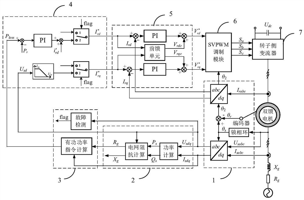
Figure 1 
Figure 2
Abstract
Description
technical field
[0001] The invention belongs to the technical field of double-fed fans, and more specifically relates to a control method and system for enhancing the synchronous stability of double-fed fans. Background technique
[0002] Short-circuit faults are common accidents in power systems. However, as the proportion of new energy power generation equipment in the power system increases, the port voltage drop caused by short-circuit faults will seriously threaten the stable operation of new energy power generation equipment. Compared with other new energy power generation equipment, the fault ride-through difficulty of doubly-fed wind generator is more difficult due to the limitation of converter capacity. In practical applications, the double-fed wind turbine usually uses a crowbar to withstand the transient current during the voltage drop immediately after detecting a grid fault, thereby effectively avoiding overvoltage and overcurrent of the rotor-side converter. ...
Examples
Embodiment
[0062] A control method to enhance the synchronous stability of doubly-fed wind turbines under deep voltage drop faults, such as figure 1 shown, including:
[0063] S1. Collect three-phase stator voltage U sabc , after coordinate transformation, the stator voltage amplitude U s , if the stator voltage amplitude U s ≤0.2, the fault detection link outputs switching signal flag=1, dq-axis rotor reference current is switched to control mode 2, otherwise, flag=0, dq-axis rotor reference current is determined by control mode 1;
[0064] S2. Calculate the active power and reactive power according to the stator voltage and current when the power grid is faulty, and then calculate the line resistance according to the voltage, active power and reactive power, and calculate the active power reference command of control mode 2 in combination with the output current of the stator port;
[0065] S3. According to the active power reference command and real-time active power, the rotor d-a...