
Rigid-flexible coupled climbing robot
A rigid-flexible coupling, robotics technology, applied in the field of robotics research and climbing robots, can solve the problems of difficulty in meeting the adaptability requirements of different rod diameters and rod-shaped objects at the same time, insufficient rigidity and limited adaptability of soft robots, etc. High cost performance, convenient control and simple structure
Patent Information
- Authority / Receiving Office
- CN · China
- Patent Type
- Applications(China)
- Current Assignee / Owner
- Publication Date
- 2021-11-16
Smart Images
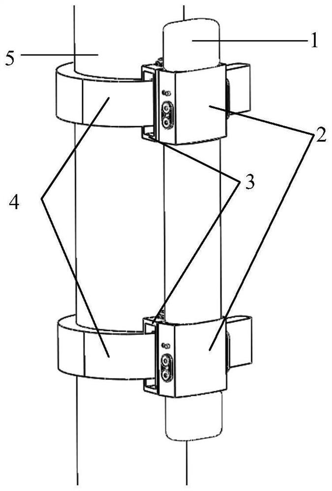
Figure 1 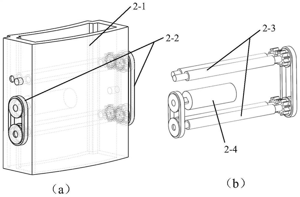
Figure 2 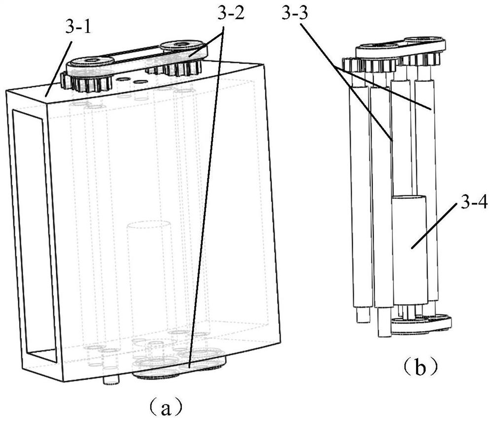
Figure 3
Abstract
Description
technical field
[0001] The patent of the present invention relates to the field of robot research, especially the field of climbing robots, and specifically relates to a portable modular rigid-flexible coupling climbing robot that can be used for climbing rods, detecting and repairing pipelines and cables. Background technique
[0002] The maintenance and operation of pipelines, cables, and trusses are difficult and high-risk tasks for humans. Using climbing robots instead of manual operations has obvious advantages in terms of safety, stability, and accuracy.
[0003] In the 1980s, the United States, Japan and other developed countries successively carried out research work on climbing robots. In the early days, Waseda University in Japan successfully developed the woody-1 tree climbing robot. The trunk moves up and down. Based on this, a large number of rigid pole-climbing robots (such as the literature "Design of a micro pole-climbing robot") have been researched, mainly...
Examples
Embodiment Construction
[0023] Such as figure 1 As shown, a rigid-flexible coupling climbing robot in this embodiment includes two annular airbags 4 for surrounding objects to be climbed, and two encircling roller drive modules fixed to one end of the two annular airbags 4 one by one. 3. One-to-one correspondence between the two telescopic roller drive modules 2 fixed to the two embracing roller drive modules 3 and the elongated airbag 1 connected between the two telescopic roller drive modules 2; The pair of rollers I3-3 for the relative movement of the annular airbag 4 passing therethrough; the telescopic roller drive module 2 is provided with the pair of rollers II2-3 for the relative movement of the elongated airbag 1 passing therethrough.
[0024] Such as figure 1 As shown, one end of the annular airbag 4 is fixed on the connecting shell of the surrounding roller driving module 3, and the annular airbag 4 surrounds the rod 5 and then passes through the two roller pairs I3-3 in the surrounding r...