
Lifting type 360-degree rotary projector and control method thereof
A projector and lifting technology, which is applied in the field of projectors, can solve problems such as troublesome adjustments, inability to adjust angles and heights, and affect projections, and achieve the effects of simple structure, increased safety, and increased adaptability
Patent Information
- Authority / Receiving Office
- CN · China
- Patent Type
- Applications(China)
- Current Assignee / Owner
- Publication Date
- 2021-12-07
Smart Images
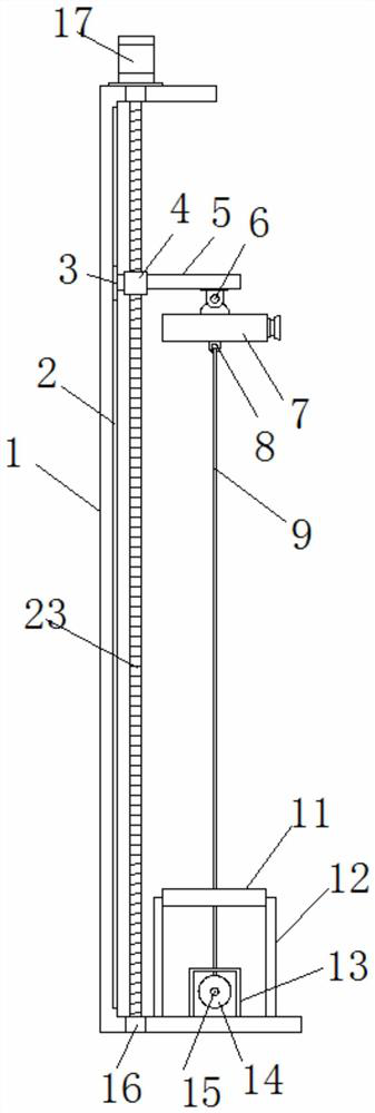
Figure 1 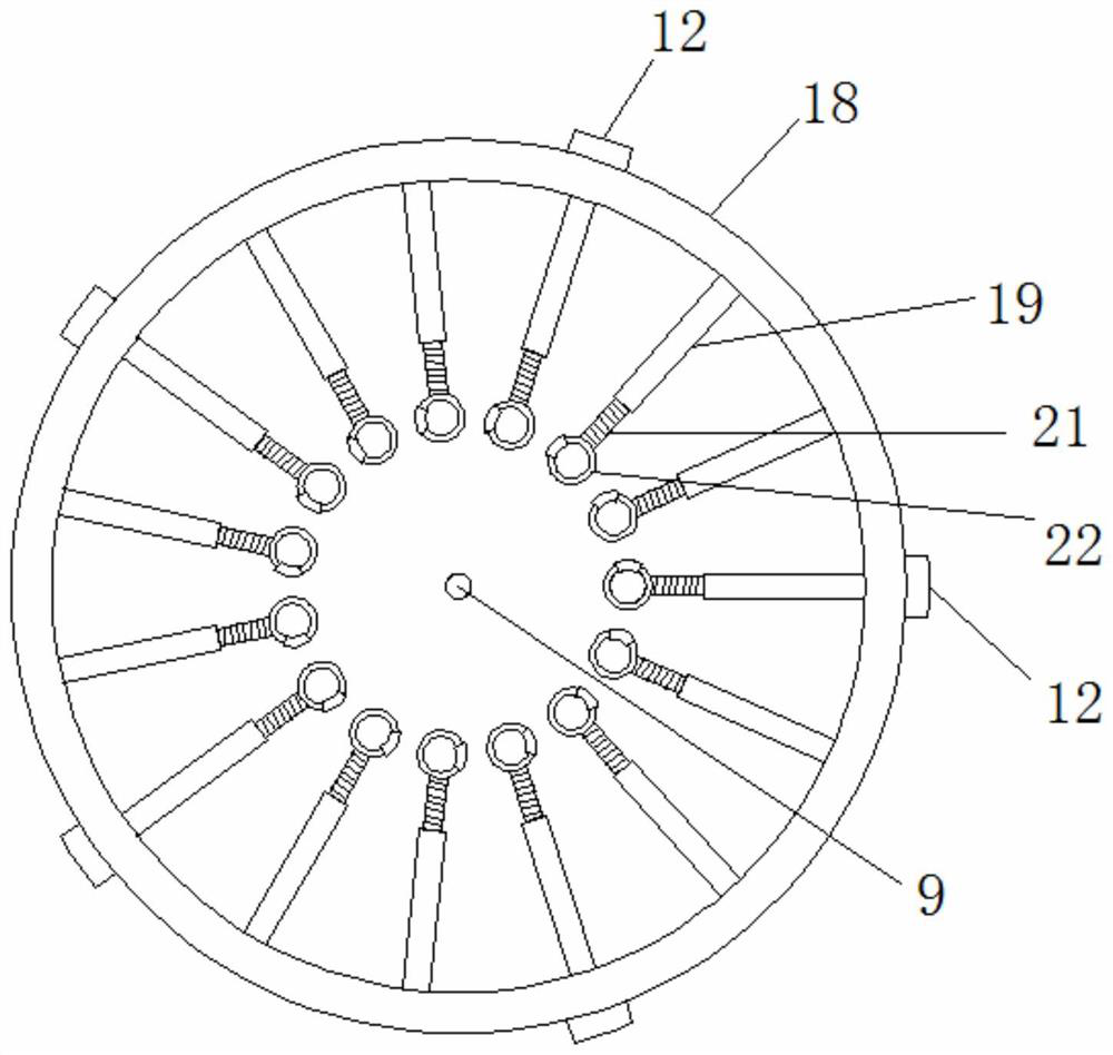
Figure 2
Abstract
Description
technical field
[0001] The invention relates to the technical field of projectors, in particular to a lift-type 360-degree rotating projector and a control method thereof. Background technique
[0002] A projector, also known as a projector, is a device that can project images or videos onto a screen. It can be connected to a computer, VCD, DVD, BD, game console, DV, etc. through different interfaces to play the corresponding video signal. Projectors are widely used in homes, offices, schools and entertainment venues.
[0003] At present, the projector is generally installed at a high place, so that after installation, its angle and height cannot be adjusted, or the adjustment is very troublesome, which affects subsequent projections. Contents of the invention
[0004] The technical problem to be solved by the present invention is to provide a lift-type 360-degree rotating projector and its control method, so as to solve the problems raised in the above-mentioned backgrou...
Examples
Embodiment Construction
[0020] Embodiments of the present invention are described in detail below, examples of which are shown in the drawings, wherein the same or similar reference numerals designate the same or similar elements or elements having the same or similar functions throughout. The embodiments described below by referring to the figures are exemplary only for explaining the present invention and should not be construed as limiting the present invention.
[0021] In describing the present invention, it is to be understood that the terms "center", "upper", "lower", "front", "rear", "left", "right", "vertical", "horizontal", The orientations or positional relationships indicated by "top", "bottom", "inner", "outer", etc. are based on the orientations or positional relationships shown in the drawings, and are only for the convenience of describing the present invention and simplifying the description, rather than indicating or implying the It should not be construed as limiting the invention ...