
Bridge splicing auxiliary equipment for water and electricity installation
A kind of auxiliary equipment and installation technology, which is applied in the field of bridge assembly auxiliary equipment for hydropower installation, can solve the problems of reducing bridge damage rate, bridge damage, lifting hands, etc., to achieve improved stability, high safety, and avoid bridge falling fall effect
Patent Information
- Authority / Receiving Office
- CN · China
- Patent Type
- Applications(China)
- Current Assignee / Owner
- Publication Date
- 2022-04-12
Smart Images
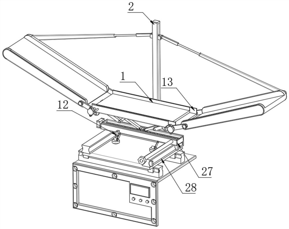
Figure 1 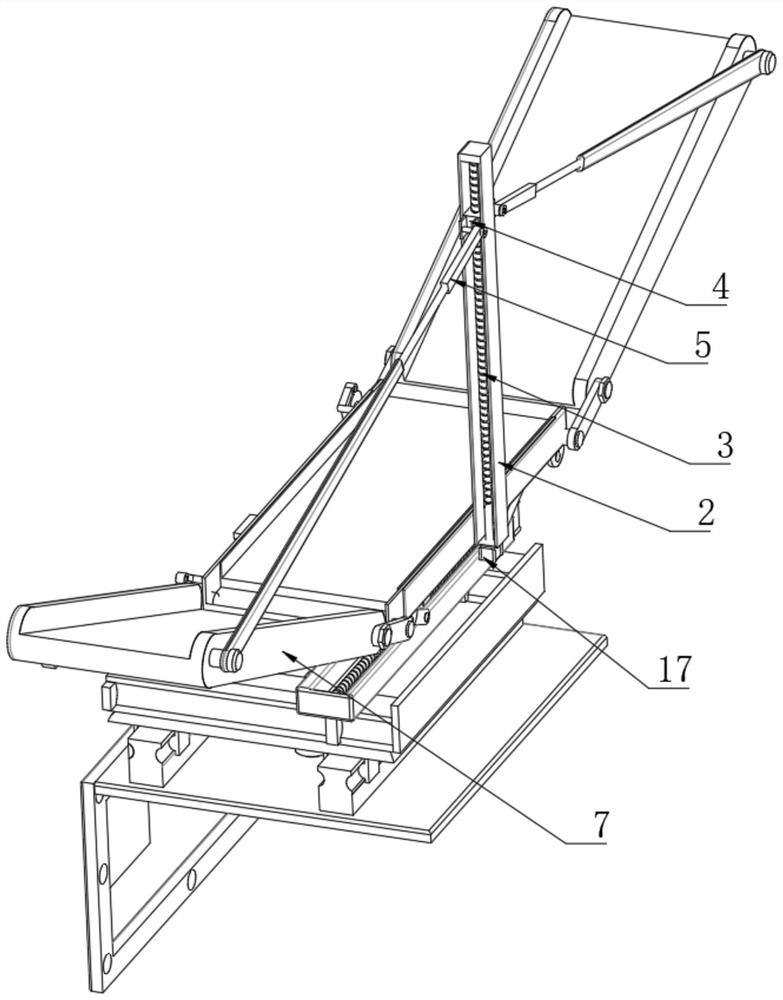
Figure 2 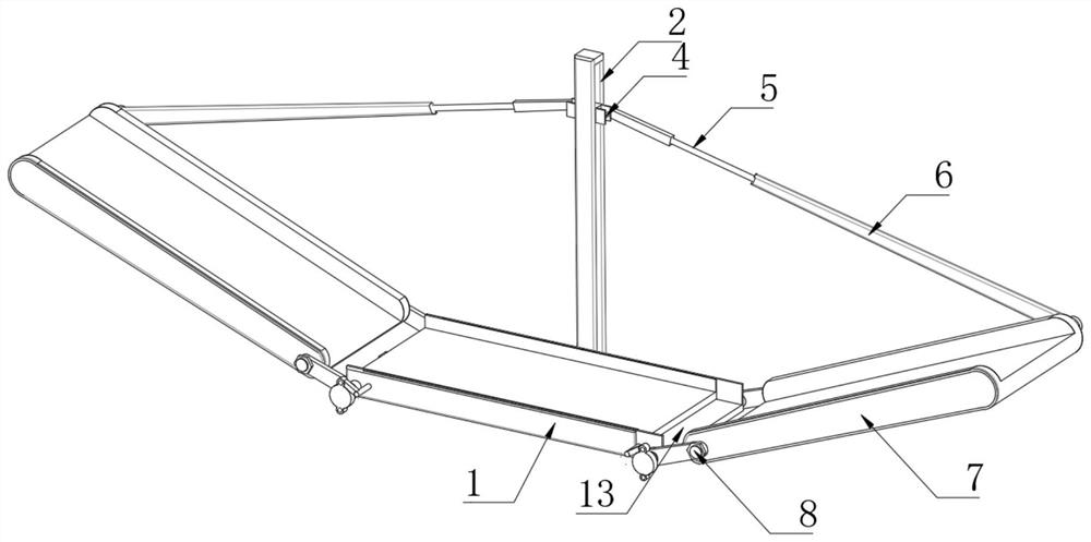
Figure 3
Abstract
Description
technical field
[0001] The invention relates to the technical field of bridge installation, and more specifically, the invention relates to an auxiliary bridge assembly equipment for hydropower installation. Background technique
[0002] Cable trays are divided into trough cable trays, tray cable trays, stepped cable trays, and grid trays. They are composed of brackets, brackets, and installation accessories. On the supports of buildings and pipe corridors, it reflects the characteristics of simple structure, beautiful appearance, flexible configuration and convenient maintenance. Auxiliary equipment is used for auxiliary operations.
[0003] In actual use, in the process of splicing the bridge, generally use the elevator to lift to the specified height, then manually lift the bridge, and carry out the butt joint operation, and for the protruding position of the beam on the wall, it is necessary to Concave inclined butt joint installation requires one person to lift and on...
Examples
Embodiment Construction
[0026]The following will clearly and completely describe the technical solutions in the embodiments of the present invention with reference to the accompanying drawings in the embodiments of the present invention. Obviously, the described embodiments are only some, not all, embodiments of the present invention. Based on the embodiments of the present invention, all other embodiments obtained by persons of ordinary skill in the art without making creative efforts belong to the protection scope of the present invention.
[0027] as attached Figure 1-9 The shown bridge assembly auxiliary equipment for hydropower installation includes a bottom support plate 1, a linkage frame 2 is installed on one side of the bottom support plate 1, and a docking mechanism is installed inside the linkage frame 2;
[0028] The docking mechanism includes a rotating helical block 4 arranged inside the linkage frame 2, and the inside of the rotating helical block 4 is provided with a collar pole 5, a...