
Landscape maintenance intelligent monitoring management device based on Internet of Things
An intelligent monitoring and management device technology, applied to wind power generation, color TV parts, TV system parts, etc., can solve the problems of position deviation and multiple fixed structures that cannot cooperate with each other, so as to prevent slipping, The effect of increasing friction
Patent Information
- Authority / Receiving Office
- CN · China
- Patent Type
- Applications(China)
- Current Assignee / Owner
- Publication Date
- 2022-07-05
Smart Images
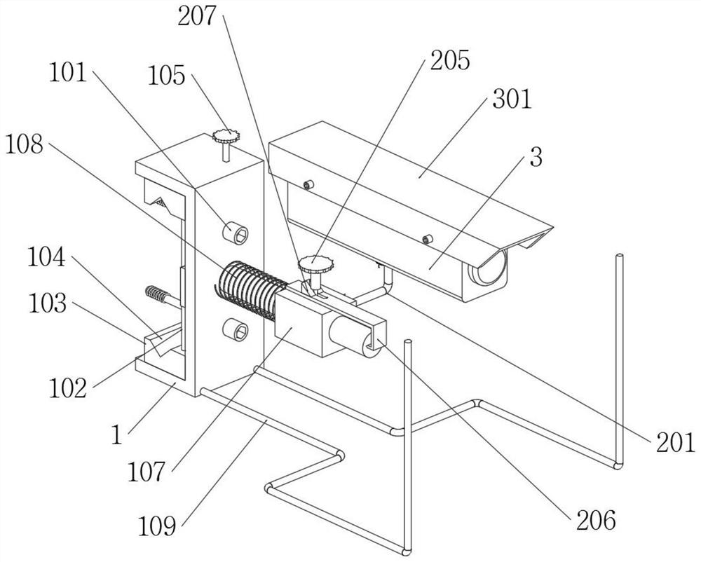
Figure 1 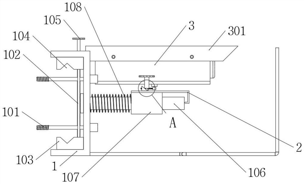
Figure 2 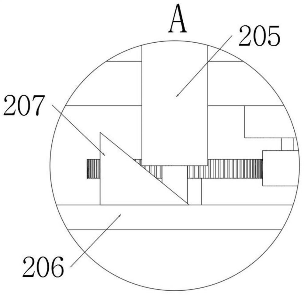
Figure 3
Abstract
Description
technical field
[0001] The invention relates to the technical field of monitoring devices, in particular to an intelligent monitoring and management device for landscape maintenance based on the Internet of Things. Background technique
[0002] With the continuous development of science and technology, the Internet of Things technology has gradually become popular. At present, monitoring and management devices controlled by the Internet of Things have become ubiquitous, and such devices need to be used in the maintenance of scenic spots.
[0003] However, as far as the current traditional landscape maintenance intelligent monitoring and management devices are concerned, first of all, when the existing devices are fixed, they are often fixed by bolts, and cannot be fixed by other structures, and multiple fixed structures cannot be mutually Second, the existing device is locked by a locking bolt when it is locked, and it is easy to cause positional deviation under the action o...
Examples
Embodiment
[0048]Example: please refer to Figure 1 to Figure 9 :
[0049] The invention proposes an intelligent monitoring and management device for landscape maintenance based on the Internet of Things, comprising: a fixed base 1 and an installation part 2;
[0050] The fixing base 1 is fixed on the utility pole by two fixing bolts 101, and the control box 4 is installed on the fixing base 1;
[0051] A mounting rod 106 is welded on the front end, and a mounting seat 107 is rotatably connected to the mounting rod 106;
[0052] The mounting part 2 consists of the mounting arm 201, the auxiliary seat A202, the locking rod A203, the driving motor A204, the locking screw 205, the locking seat 206, the auxiliary block 207, the card slot A208, the auxiliary seat B209, the locking rod B210, the card slot B211 and the drive The motor B212 is formed, and the mounting arm 201 is rotatably connected to the mounting seat 107;
[0053] The camera 3 is rotatably connected to the mounting arm 201 ...