
Rotary compressor and method for manufacturing the same
A rotary compressor and rotary compression technology, which is applied to rotary piston machines, rotary piston pumps, machines/engines, etc., can solve the problems of large gap between blade grooves and blades, low machining accuracy, and refrigerant leakage, etc., to achieve Effects of suppressing gap leakage, improving machining accuracy, and reducing gaps
Patent Information
- Authority / Receiving Office
- CN · China
- Current Assignee / Owner
- Publication Date
- 2005-03-16
Smart Images
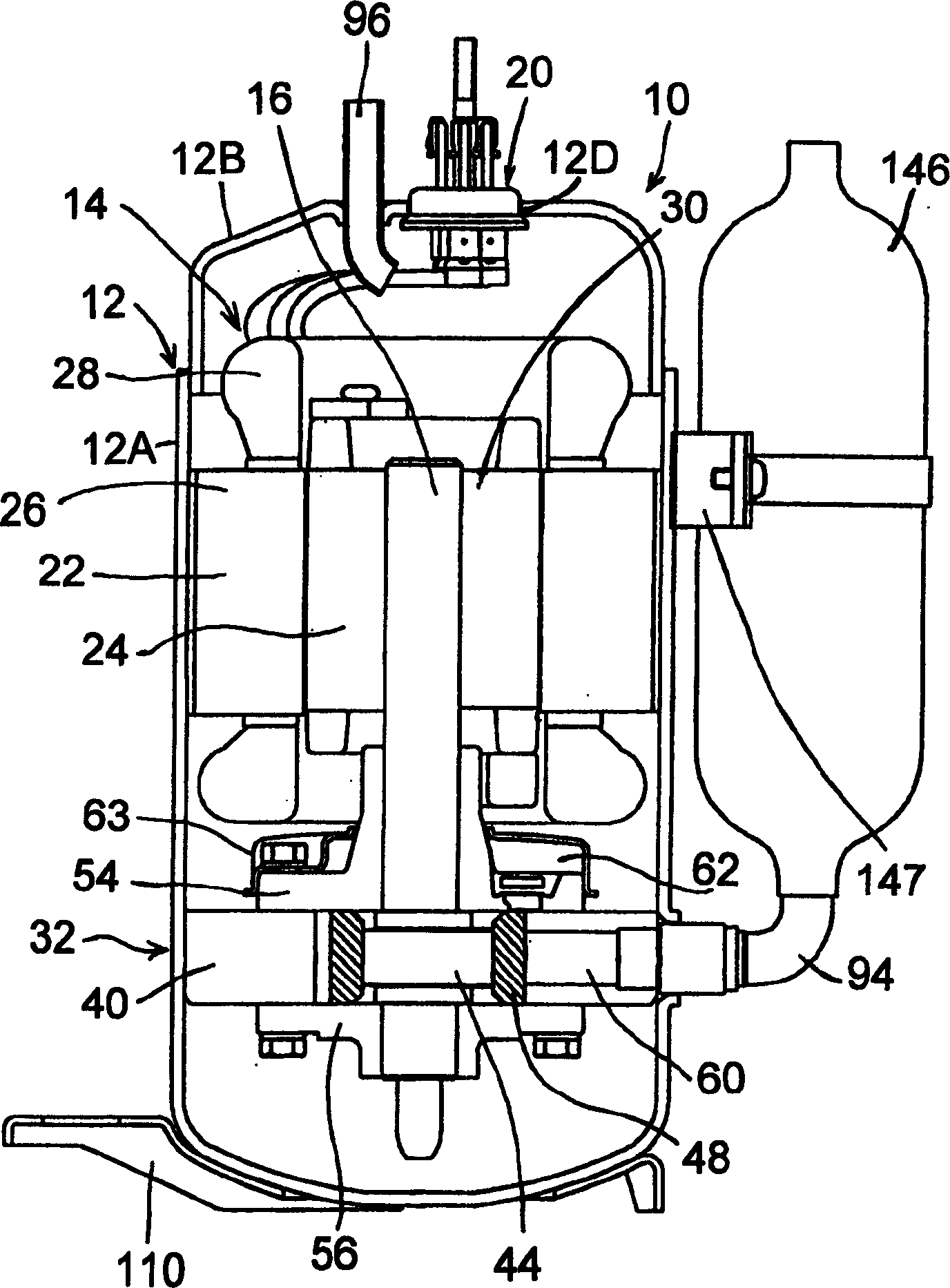
Figure 1 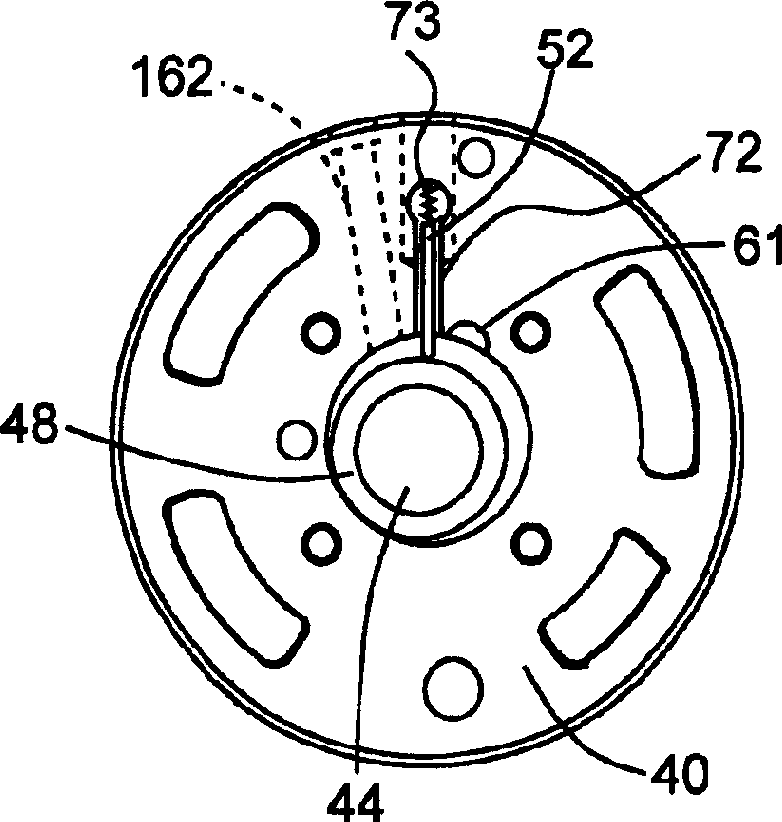
Figure 2 
Figure 3
Abstract
Description
technical field
[0001] The present invention relates to a rotary compressor provided with a rotary compression element driven by a rotary shaft of the drive element and a method of manufacturing the same. Background technique
[0002] In conventional rotary compressors of this type, refrigerant is sucked into the low-pressure chamber side of the cylinder from the suction port of the rotary compression element, compressed by the action of the rollers and vanes, and then discharged to the outside from the discharge port of the high-pressure chamber side of the cylinder. The roller is installed in the cylinder, fits in the eccentric part of the rotating shaft, and rotates eccentrically in the cylinder. The upper and lower openings of the rollers and cylinders are closed by support members. In addition, vane grooves are provided in the radial direction of the cylinder, and the vanes are movably mounted in the vane grooves (see Japanese Patent Application Laid-Open No. 8-47207)....
Examples
Embodiment 1
[0022] figure 1 It is a vertical cross-sectional view showing a vertical internal high-pressure single-stage rotary compressor 10 including a rotary compression element 32 as an embodiment of the present invention. exist figure 1 Among them, the rotary compressor 10 is an internal high-pressure single-stage rotary compressor using fluorine-based refrigerant R410A as a refrigerant. The rotary compressor 10 is composed of a hermetic container 12 as a casing, an electric element 14 as a driving element, and a rotary compression element 32 . The airtight container 12 is constituted by a cylindrical container body 12A made of steel plate and a substantially bowl-shaped end cap (lid body) 12B that closes the upper opening of the container body 12A. The electric element 14 is disposed above the internal space of the container body 12A of the airtight container 12 . The rotary compression element 32 is arranged below the electric element 14 and is driven by the rotation shaft 16 ...
Embodiment 2
[0054] In Embodiment 1, the end surface area A of the roller 48 and the rotational compression element 32 are excluded by notching the inner side (the side of the eccentric portion 44 ) of the contact surface of the roller 48 which is in contact with the upper support member 54 and the lower support member 56 . The ratio A / B of volume B is set to 30mm 2 / cm 3 ~60mm 2 / cm 3 , but not limited thereto, it is also possible to change the shape of the eccentric portion 44, or the inner side of the expansion roller 48, to increase the contact area with the upper support member 54 and the lower support member 56, etc., so that the end surface area A of the roller 48 is related to the rotation The ratio A / B of the exclusion volume B of the compression element 32 is set to 30mm 2 / cm 3 ~60mm 2 / cm 3 . Also in this way, the same effect as that of the above-mentioned embodiment can be obtained.
Embodiment 3
[0056] In Embodiment 1 and Embodiment 2, the cylinder of the rotary compressor 10 adopts figure 2 Shown circular cylinder 40, but not limited thereto, for example, can also be used Figure 5 The shown cuttlefish-shaped air cylinder can also obtain the same effects as those of the above-mentioned embodiments.