
Bearing having threaded rollers
Patent Information
- Authority / Receiving Office
- US · United States
- Current Assignee / Owner
- Publication Date
- 2021-11-23
Smart Images
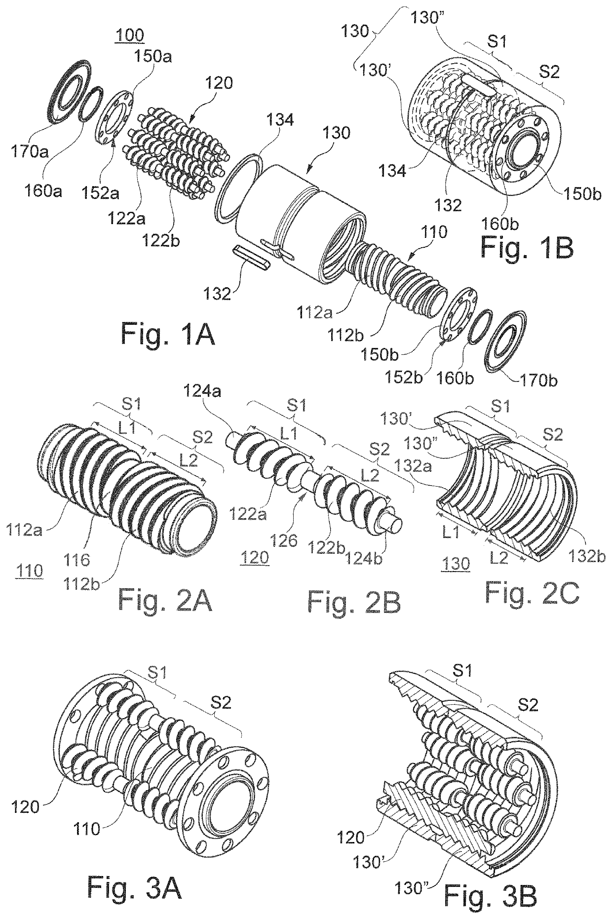
Figure 1 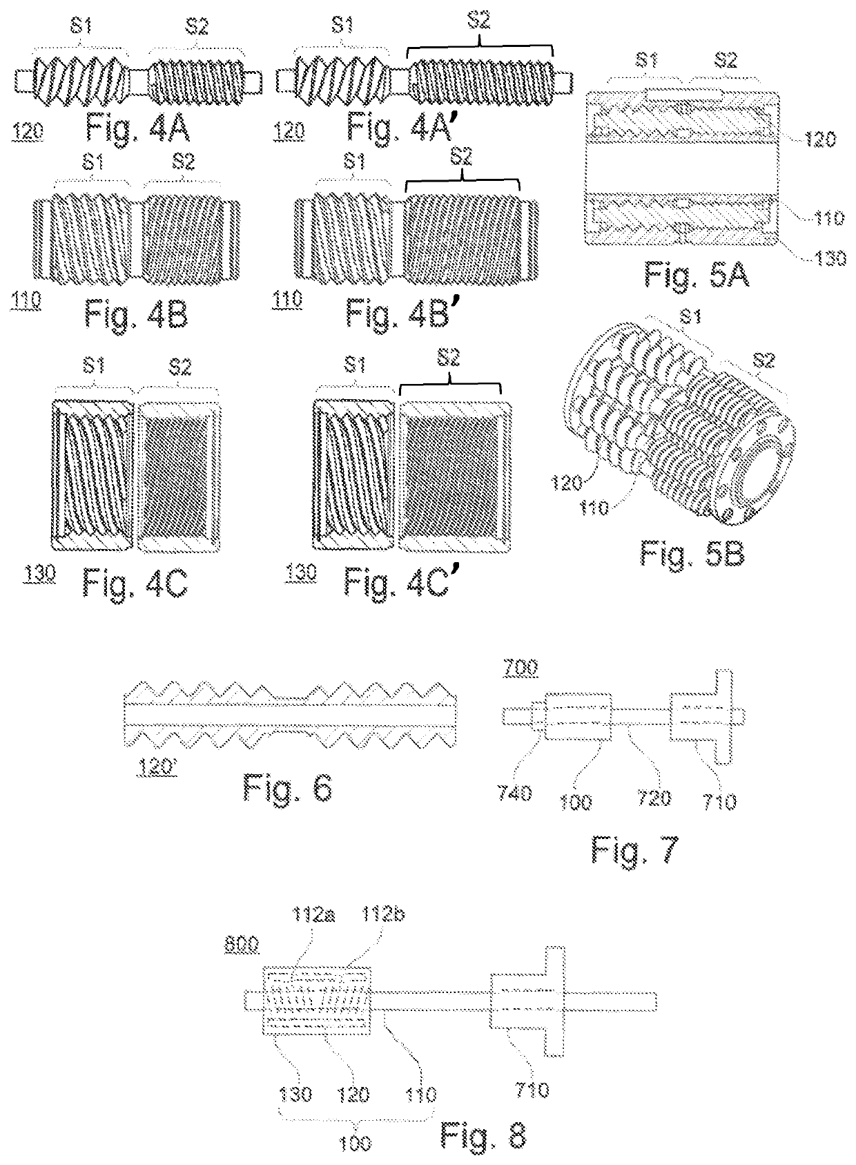
Figure 2
Abstract
Description
CROSS REFERENCE TO RELATED APPLICATIONS
[0001] This application is the U.S. National Stage of PCT / FR2018 / 053013 filed on Nov. 27, 2018, which application claims priority under 35 USC § 119 to French Patent Application No. 17 61592 filed on Dec. 4, 2017. Both of these applications are hereby incorporated by reference in their entirety.TECHNICAL FIELD
[0002] The invention relates to the field of rolling bearings, such a bearing being a mechanism that supports and guides an assembly in rotation.BACKGROUND OF THE INVENTION
[0003] Conventional rolling bearings include ball bearings, tapered roller bearings, or indeed cylindrical roller bearings, and such conventional bearings are the most widely used because of their low cost, with the drawback of being of large overall size in particular when they are dimensioned to bear high loads.
[0004] Rolling bearings exist that are based on systems of rollers having screw threads or grooves and that are more costly than conventional bearings but that have...
Examples
Embodiment Construction
[0034]A rolling bearing mechanism of the invention is shown in FIGS. 1A and 1B, 2A to 2C, 3A and 3B, 4A to 4C, 4A′ to 4C′, 5A and 5B, 6, 7, and 8.
[0035]FIG. 1A shows a particular rolling bearing mechanism, taken by way of example for illustrating the main elements making up a rolling bearing mechanism of the invention.
[0036]It should be understood that neither the invention nor the present embodiment are limited to this particular situation.
[0037]As shown in FIG. 1A, a rolling bearing mechanism 100 may comprise a rod 110, an outer ring 130 disposed around the rod, surrounding it coaxially, and a plurality of rollers 120 interposed between the rod and the outer ring and having their longitudinal axes parallel to the longitudinal axes of the rings.
[0038]The rod 110 may be solid or hollow, and when it is hollow, it may also be referred to as an “inner ring”; the rod 110 may extend longitudinally on either side of the outer ring 130, e.g. as in the device shown in FIG. 8.
[0039]As shown ...