
Wheel structure
a technology of wheels and wheels, applied in the field of wheels, can solve the problems of increasing the cost of manufacture and assembly, difficulty in controlling the turning movement, and carts (a) still may encounter the possibility of overturning, so as to save assembly time, reduce manufacturing costs, and stable riders
Patent Information
- Authority / Receiving Office
- US · United States
- Patent Type
- Applications(United States)
- Current Assignee / Owner
- Publication Date
- 2006-09-14
- Estimated Expiration
- Not applicable · inactive patent
Smart Images
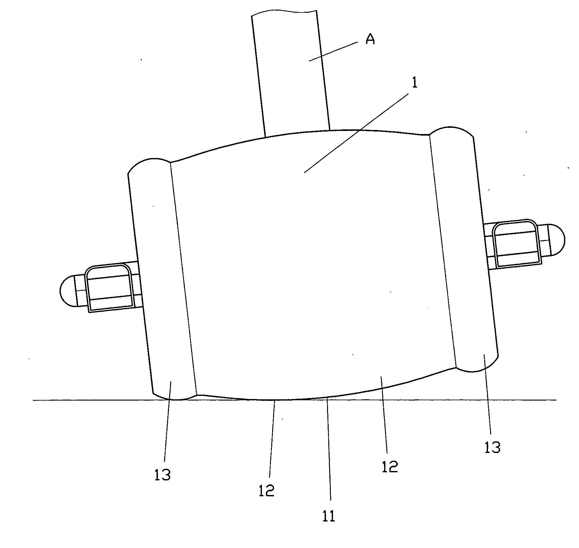
Figure 1 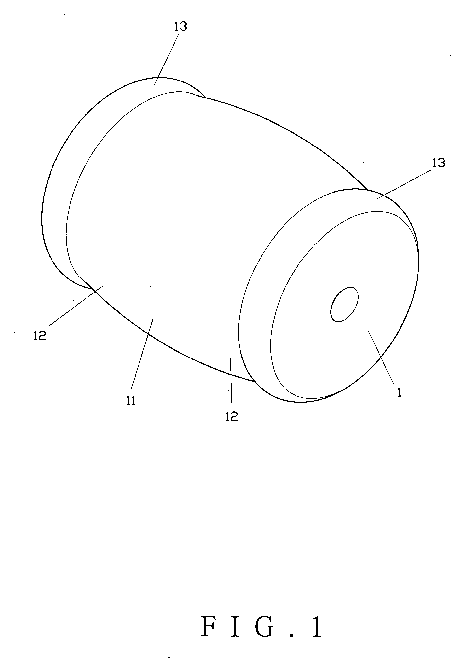
Figure 2 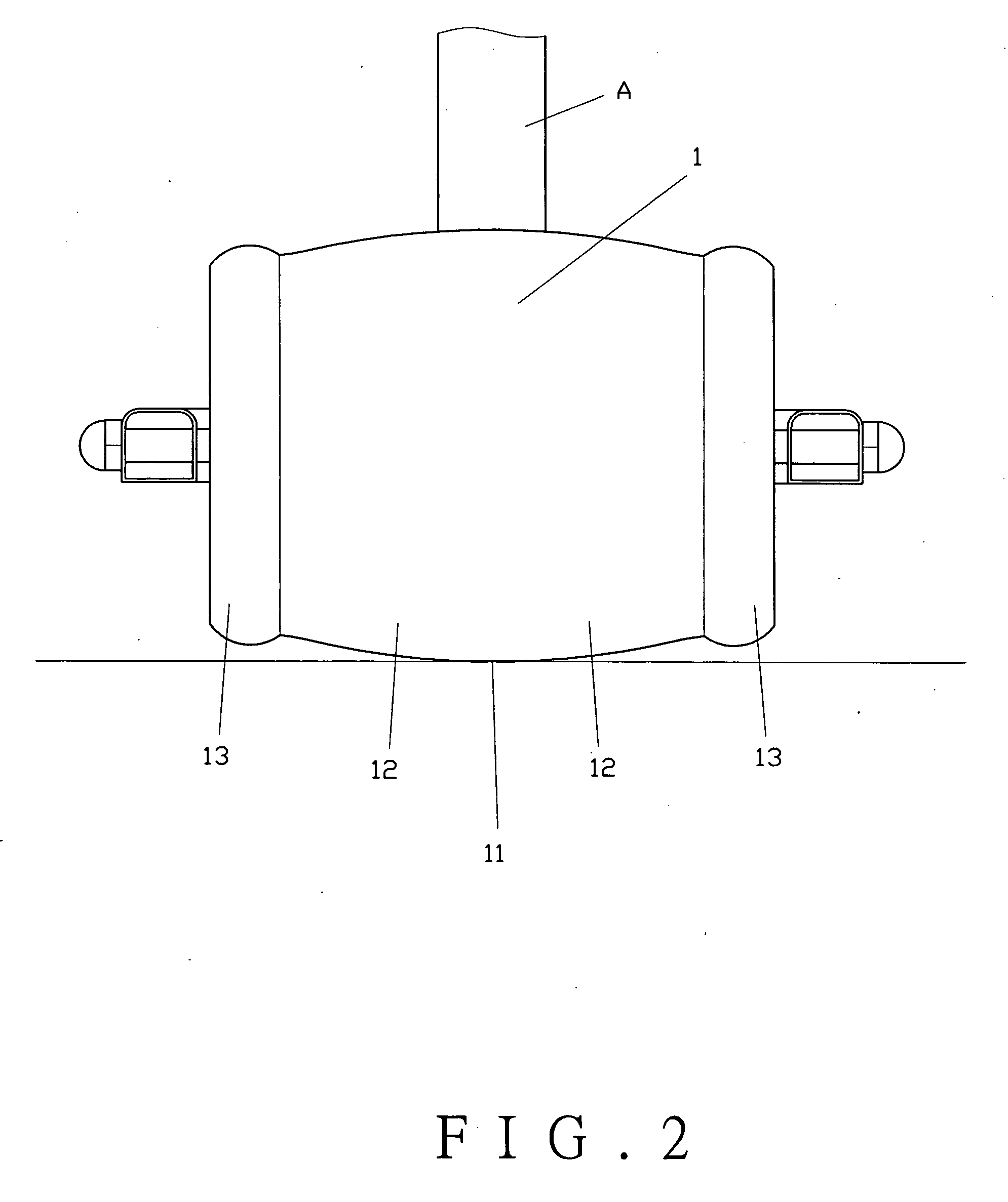
Figure 3
Abstract
Description
BACKGROUND OF THE INVENTION
[0001] 1. Field of the Invention
[0002] This invention relates to a wheel structure applied to playing or sporting vehicles such as scooters, tricycles, bicycles, skateboards, roller skates, training cycles, hand-pulling suitcases, hand carts, shopping carts, toy carts or balancing wheels, and more particularly to a wheel having two auxiliary sections at respective sides of a main wheel body to increase contact surfaces of the wheel with the ground.
[0003] 2. Description of the Prior Art
[0004] Most scooters, tricycles or bicycles for children are mounted with wheels (B) to a cart (A), as shown in FIG. 8, to facilitate movement of the cart (A). When the cart (A) makes a turn, it is difficult to control turning movement because the wheels (B) are small in size. Sometimes the cart (A) may even turnover if the turn is made too wide.
[0005] In order to correct the shortcoming, an egg-shaped wheel (C) was derived, as shown in FIG. 9, to provide the stability w...
Examples
first embodiment
[0021] As shown in FIG. 1, the present invention comprises a wheel (1) having a main wheel body (11) at the center portion for direct contact with the ground. The main wheel body (11) has its two sides extending to form a pair of extension sections (12) to get in touch with the ground when making turns. Each extension section (12) extends outwardly to form an auxiliary section (13). The main wheel body (11) of the wheel (1) has a larger outer diameter than the outer diameters of the auxiliary sections (13) to increase the contact surfaces with the ground when making turns. The auxiliary sections (13) are integral to the main wheel body (11).
[0022] To operate the present invention, as shown in FIGS. 2 and 3, the wheel (1) is pivotally connected to a cart (A). When the cart (A) is rolling in a straight direction, the main wheel body (11) of the wheel (1) remains contact with the ground. When the cart (A) makes a turn, due to the centrifugal force, the wheel (1) will incline with the c...
second embodiment
[0023] the present invention comprises a wheel (1A) as shown in FIG. 4. The wheel (1A) has a main wheel body (11A) at the center portion, a pair of extension sections (12A) extending from respective sides of the main wheel body (11A), and a pair of auxiliary sections (13A) coaxially extending from the extension sections (12A), respectively. The main wheel body (11A) of the wheel (1A) has a larger outer diameter than the outer diameters of the auxiliary sections (13A). The extension sections (12A) are spaced from the auxiliary sections (13A).
third embodiment
[0024] the present invention comprises a wheel (1B), as shown in FIG. 5. The wheel (1B) comprises a main wheel body (11B) at the center portion to be in touch with the ground when the cart is rolling. The main wheel body (11B) has its two sides extending outwardly to form a pair of extension sections (12B) and a pair of auxiliary sections (13B) coaxially extending from the extension sections (12B), respectively. The main wheel body (11B) of the wheel (1B) has a larger outer diameter than the outer diameters of the auxiliary sections (13B). The extension sections (12B) are spaced from the auxiliary sections (13B).