
Bone anchoring device
a bone anchoring device and rod technology, applied in the field of bone anchoring devices, can solve the problems of difficult time-consuming, difficult adjustment of the rod position relative to the receiving part, and inability to continue positioning, and achieve the effect of facilitating the handling of the bone anchoring device during surgery
Patent Information
- Authority / Receiving Office
- US · United States
- Patent Type
- Applications(United States)
- Current Assignee / Owner
- Publication Date
- 2008-05-15
- Estimated Expiration
- Not applicable · inactive patent
Smart Images
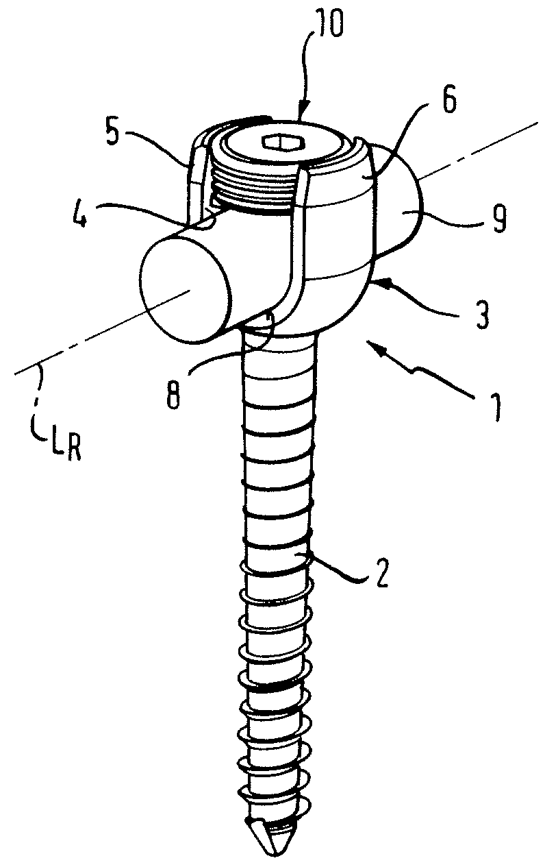
Figure 1 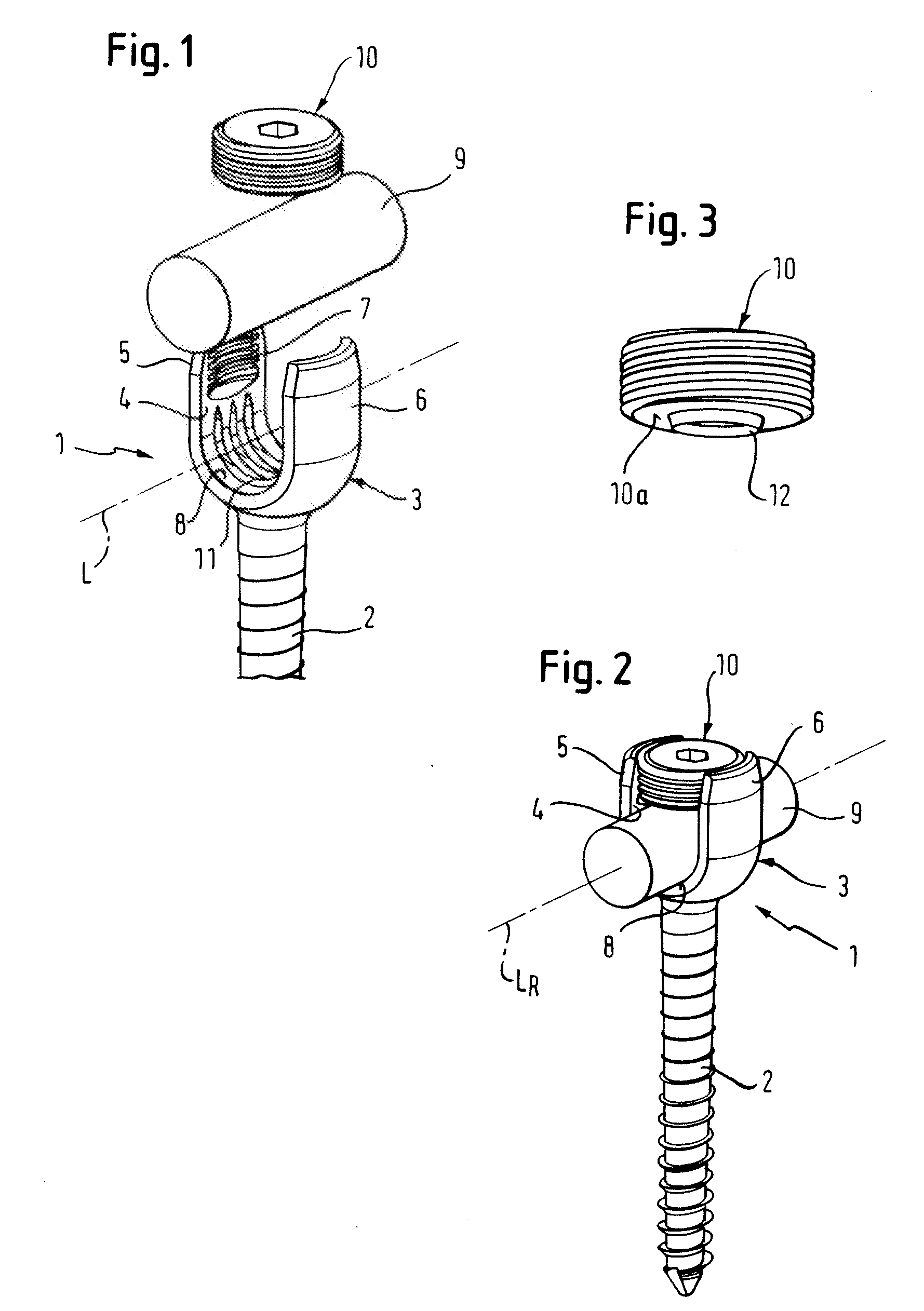
Figure 2 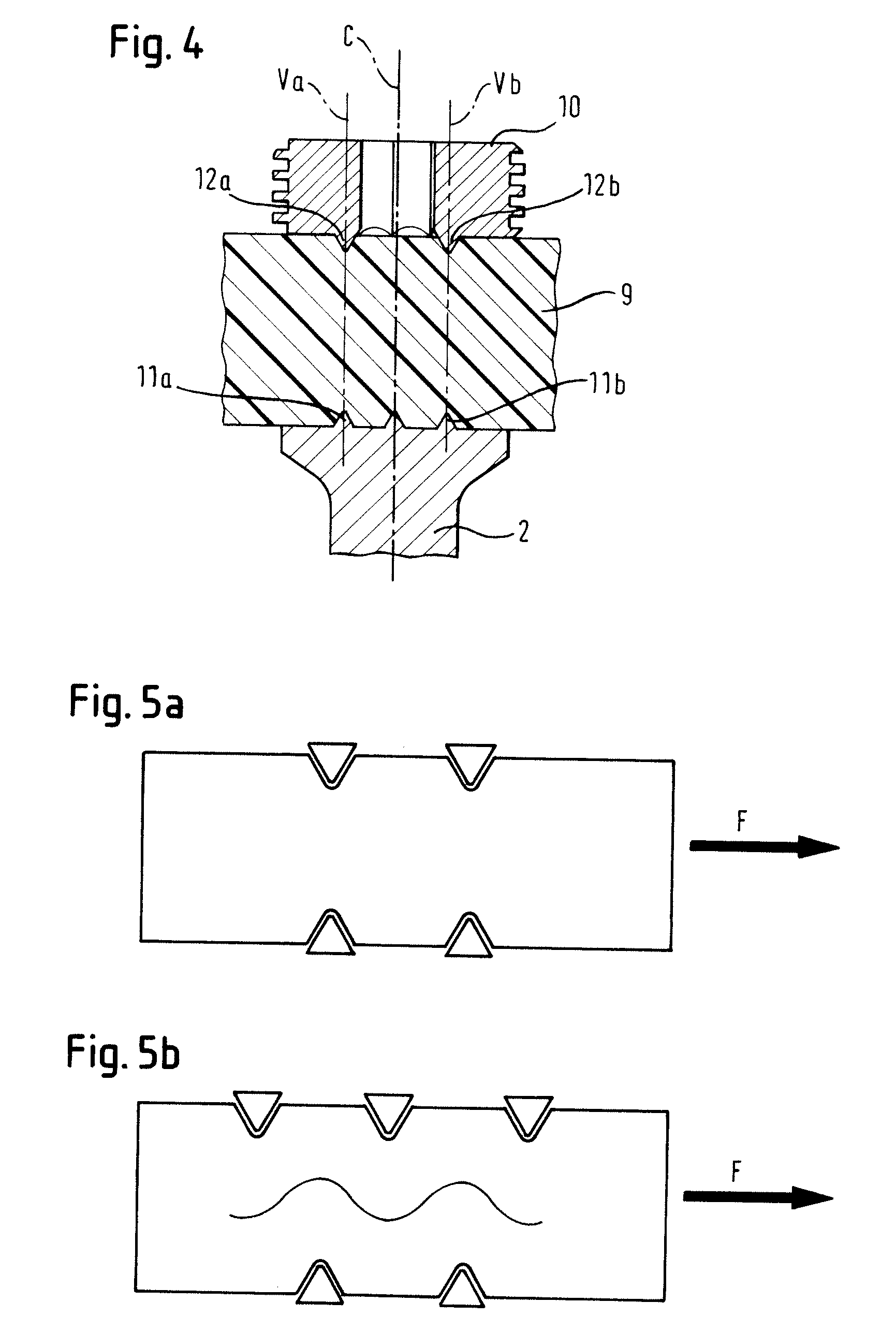
Figure 3
Abstract
Description
CROSS-REFERENCE TO RELATED APPLICATIONS
[0001] The present application claims the benefit of U.S. Provisional Patent Application Ser. No. 60 / 825,841, filed Sep. 15, 2006, and claims priority from European Patent Application EP06019341.4, filed Sep. 15, 2006, the entire disclosures of which are incorporated herein by reference.BACKGROUND
[0002] The present application generally relates to a bone anchoring device for the dynamic stabilization of bones, in particular for the dynamic stabilization of the spine, and in particular, to a bone anchoring element which can be connected with a flexible rod which has a smooth surface and which is made of an elastic material.
[0003] Bone anchoring devices comprising a bone screw and a flexible rod which is made of an elastic material are known from EP 1 364 622 A2 and EP 1 527 742 A1. The rod has a corrugated surface which cooperates with a rib structure provided on the bottom of the receiving part of the bone screw to form a form-fit connection. The ...
Examples
first embodiment
[0026]As shown in FIGS. 1 to 4 the bone anchoring device comprises a bone anchoring element 1 in the form of a monoaxial bone screw having a shank 2 with a bone thread and a tip at one end and a receiving part 3 at the opposite end. The receiving part 3 is substantially cylindrically-shaped and comprises a substantially U-shaped recess 4 forming two free legs 5,6. An internal thread 7 is provided on the legs. The bottom of the U-shaped recess forms a seat 8 for receiving a rod 9. The rod 9 is used to connect several bone anchoring elements. To secure the rod 9 in the recess 4, a locking element in the form of an inner screw 10 is provided which can be screwed-in between the legs 5, 6.
[0027]As can be seen in particular in FIGS. 1 and 4 a plurality of rib-like projections 11 are provided on the surface of the seat 8. The rib-like projections 11 extend in a direction perpendicular to the longitudinal axis L of the recess 4 and hence extend perpendicular to the longitudinal axis LR of ...
second embodiment
[0036]FIG. 6 to 14 show the bone anchoring device. The bone anchoring device comprises a bone anchoring element 20 in the form of a polyaxial bone screw having a screw element with a shank 21 with a bone thread, a tip at one end and a spherical head 22 at the opposite end. A recess 23 for engagement with the screwing-in tool is provided at the side of the head 22 which is opposite to the shank.
[0037]The bone anchoring element 20 further comprises a receiving part 25 which has a first end 26 and a second end 27 opposite to the first end and a central axis C intersecting the plane of the first end and the second end. Coaxially with the central axis C a bore 29 is provided which extends from the first end to a predetermined distance from the second end. At the second end 27 an opening 30 is provided the diameter of which is smaller than the diameter of the bore 29. The head 22 is pivotably held in the receiving part 25 with the shank extending through the opening 30.
[0038]The receiving...