
Method and device for an inner-tube
Patent Information
- Authority / Receiving Office
- US · United States
- Current Assignee / Owner
- Publication Date
- 2009-02-12
- Estimated Expiration
- Not applicable · inactive patent
Smart Images
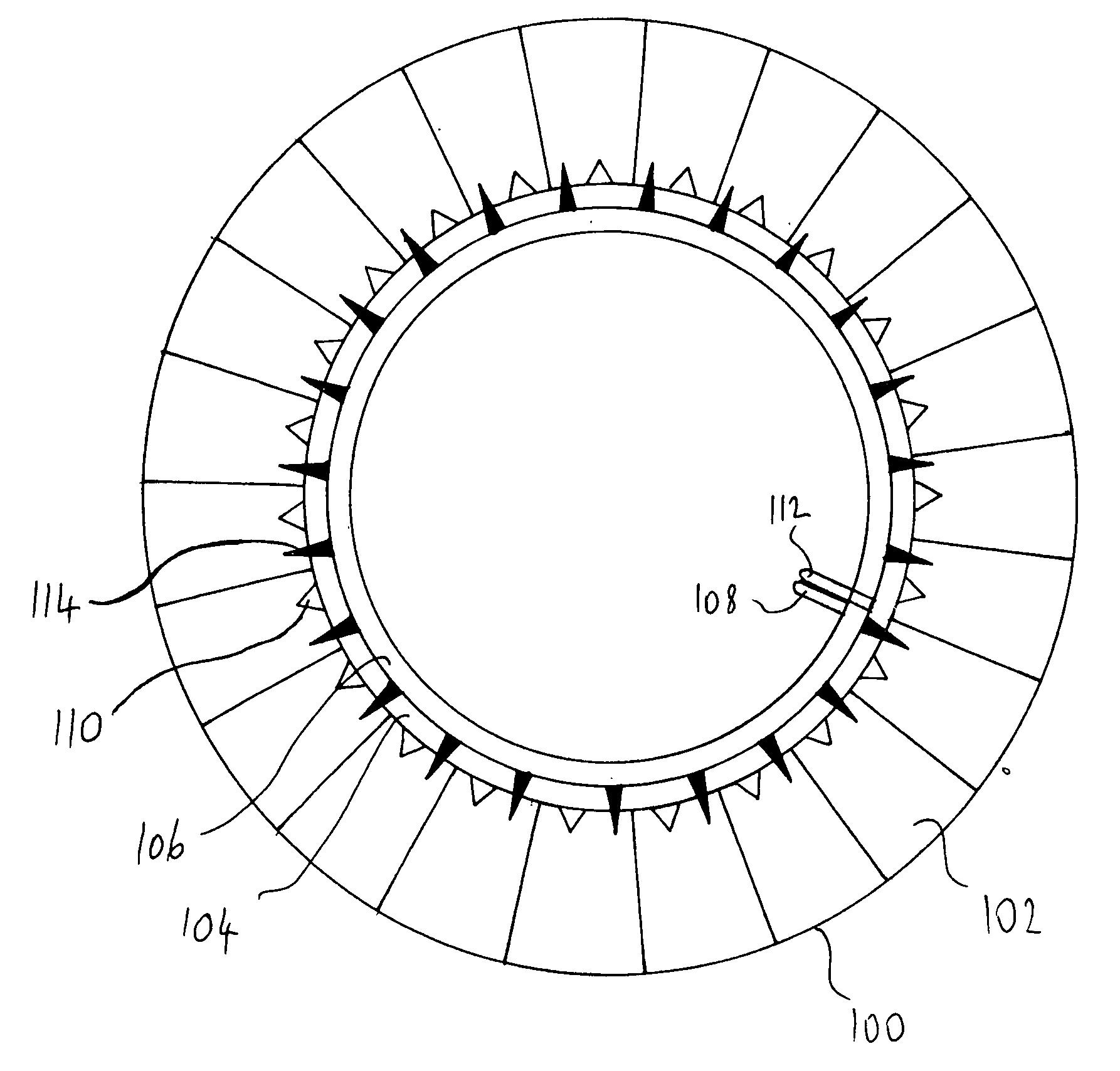
Figure 1 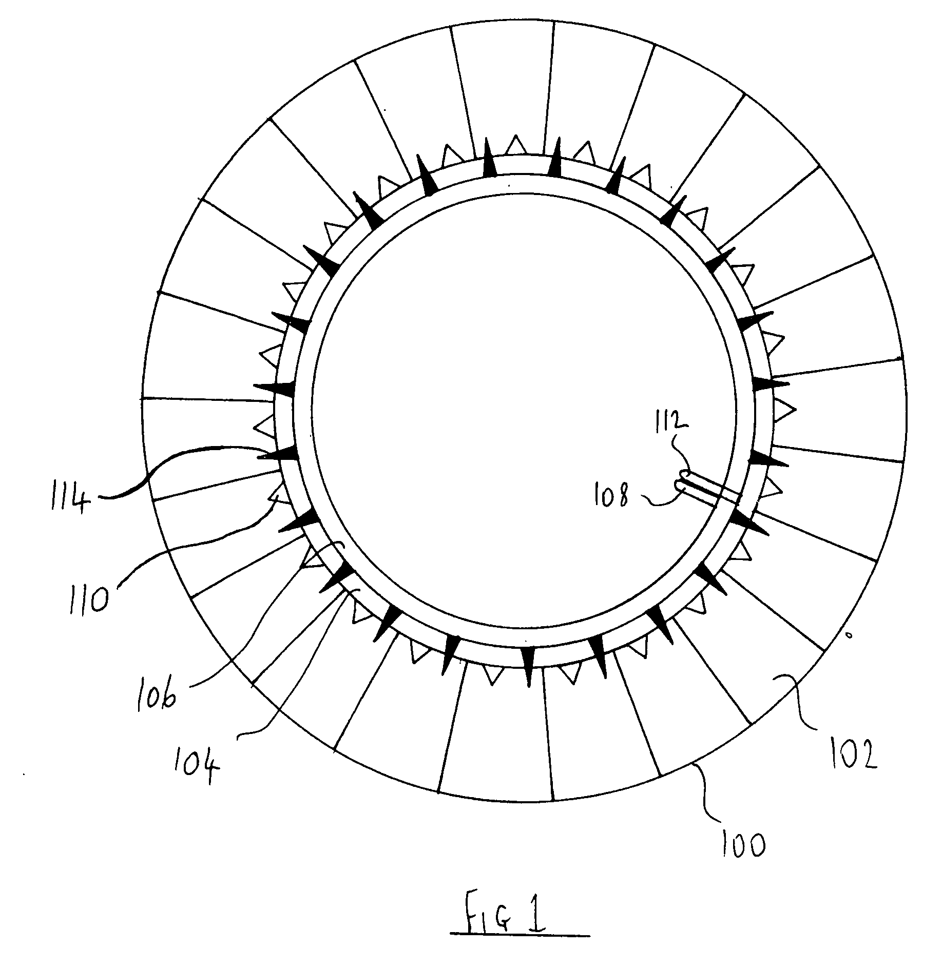
Figure 2 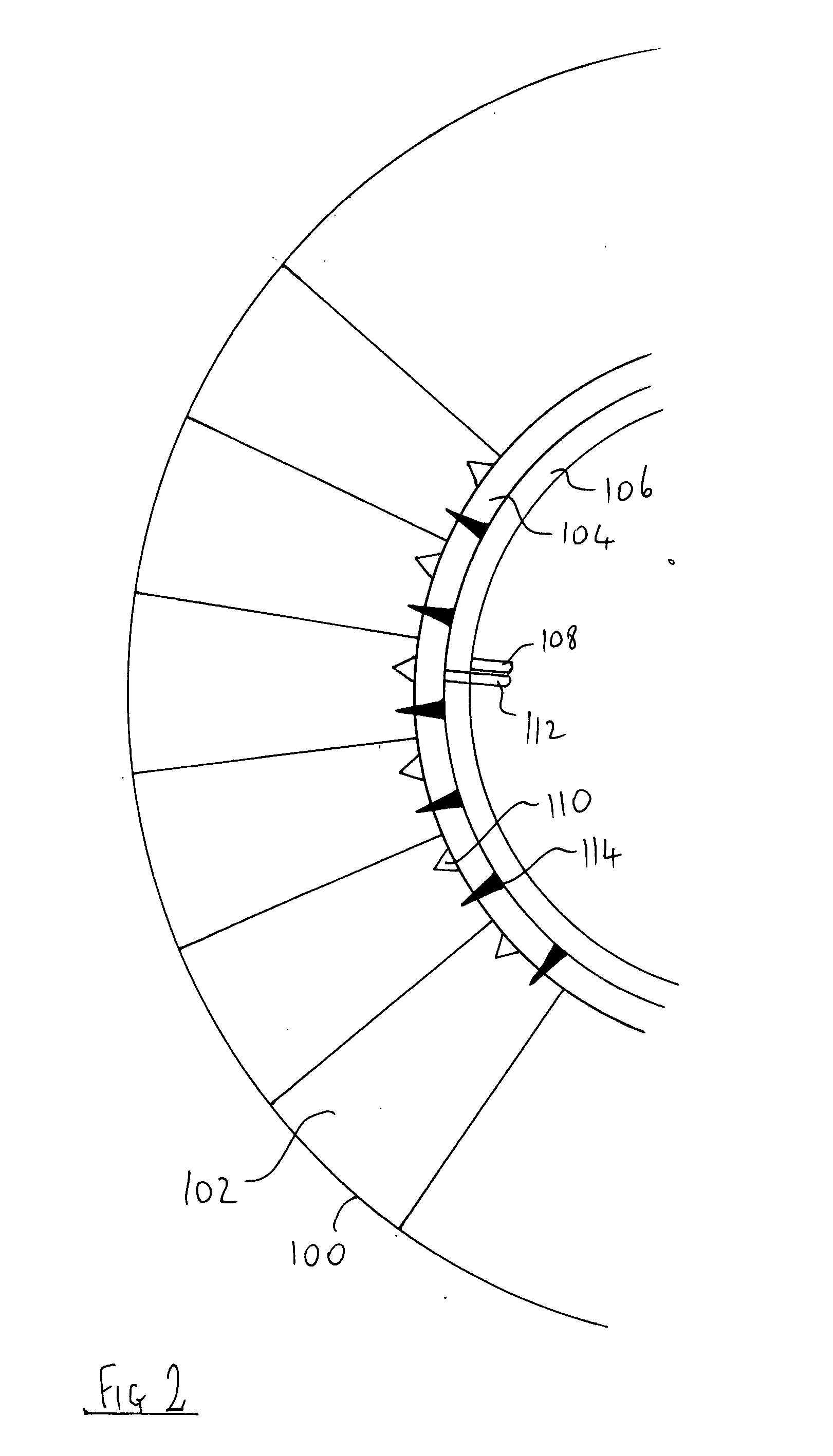
Figure 3
Abstract
Description
FIELD OF THE INVENTION
[0001] This invention is in the field of pneumatic tires and in particular an inner-tube that will not lose all its air when punctured.BACKGROUND OF THE INVENTION
[0002] The phenomenum of punctures in pneumatic tires is well known. The problems and dangers involved with punctures in tires applies to tubeless tires and tires with inner-tubes. When even a small hole punctures an inner-tube, the inner-tube usually loses all its air in a very short time. Tubeless tires lose their air slower when the hole is small but larger holes or gashes can cause the air to leave the tire in a few seconds. This presents a number of problems that may be divided into three main categories namely, safety, convenience and costs.
[0003] Some of the safety problems of the inner-tube are;
[0004] a. Accidents including fatal accidents caused by people changing the flat tire at the side of the road or other dangerous place where passing traffic does not see or can not see a person at the edge o...
Examples
Embodiment Construction
[0042]As will be appreciated the present invention is capable of other and different embodiments than those discussed above and described in more detail below, and its several details are capable of modifications in various aspects, all without departing from the spirit of the invention. Accordingly, the drawings and description of the embodiments set forth below are to be regarded as illustrative in nature and not restrictive.
[0043]FIG. 1 shows an inner-tube of this invention 100 whose outer section is divided into many cells 102. There are two more small sized tubes adjacent to the main tube 102, namely the inflation tube 104 and the deflation tube 106. The inflation tube 104 is for filling the inner-tube with air. The air pump connection main valve 112 is capable of being coupled with an air pump that would pump in air to the inflation tube 104 and from there the air would flow through the one way valves 110 into the individual cells 102. The one way valves 110 allow air to enter...