
Optical Operating Apparatus
Patent Information
- Authority / Receiving Office
- US · United States
- Current Assignee / Owner
- Publication Date
- 2009-11-19
Smart Images
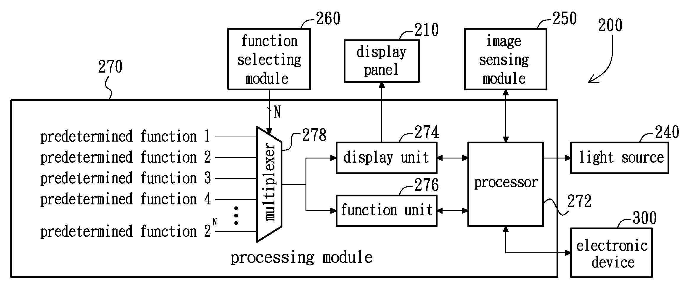
Figure 1 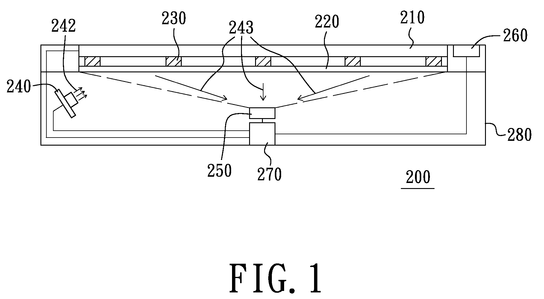
Figure 2 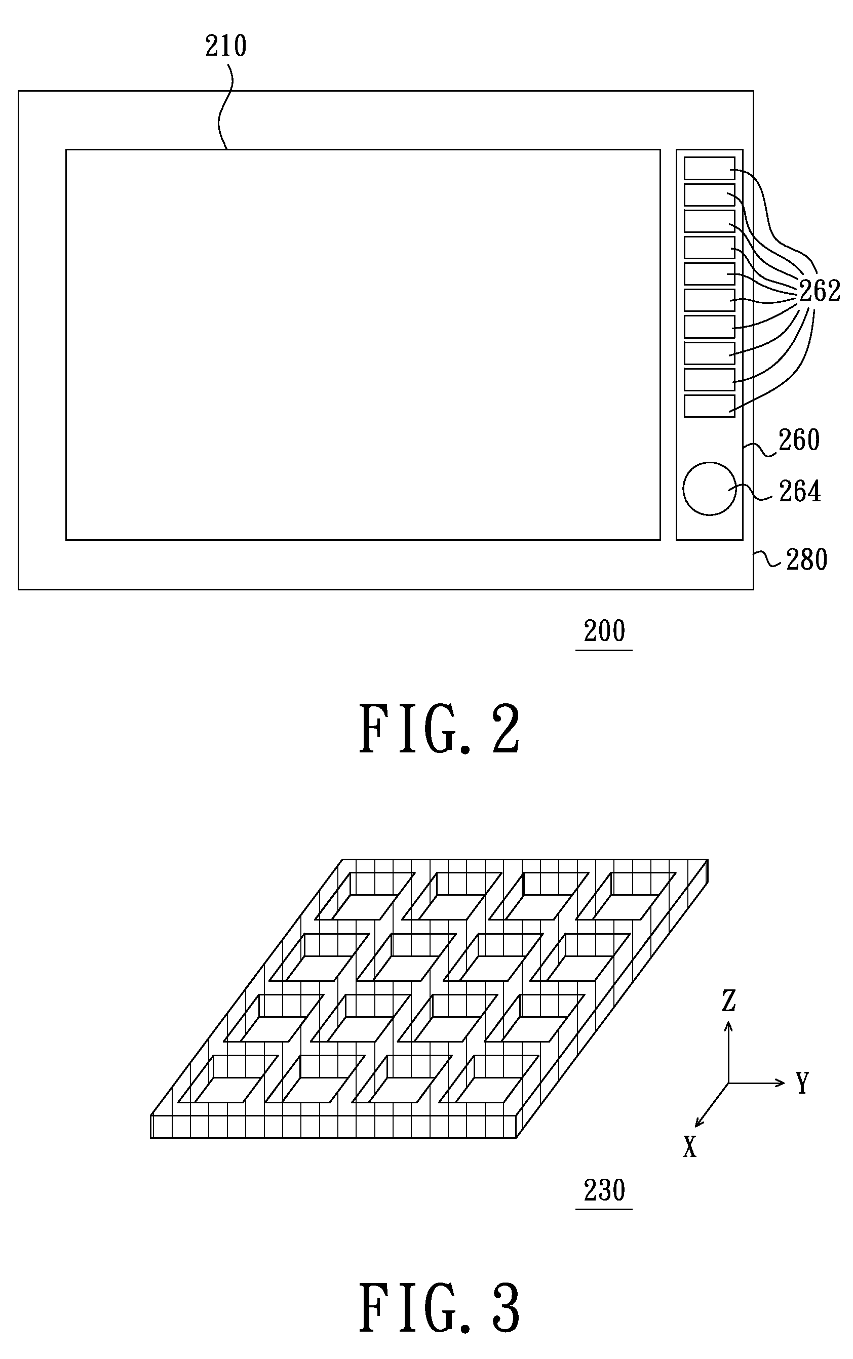
Figure 3
Abstract
Description
[0001] This application is a continuation-in-part application of U.S. patent application Ser. No. 12 / 119,641, filed on May 13, 2008.BACKGROUND
[0002] 1. Field of the Invention
[0003] The present invention relates to an operating apparatus, particularly, to an optical operating apparatus.
[0004] 2. Description of Related Art
[0005] With the development of flat panel display technology, more and more electronic products have a screen. In these electronic products, many products are operated by moving the cursors in the screens. Generally, two typical operating apparatuses, i.e., resistive operating apparatus and capacitive operating apparatus, are used to move the cursor in the screen. Because the resistive operating apparatus has low sensitivity, in practical application, the resistive operating apparatus is prone to suffer too much pressure and tends to be damaged. In addition, the capacitive operating apparatus has high price, and is easy to cause operating error because of electrostatic fo...
Examples
Embodiment Construction
[0028]FIG. 1 is a schematic view of an optical operating apparatus of an embodiment of the present invention, FIG. 2 is a top view of the optical operating apparatus of FIG. 1 and FIG. 3 is a three-dimensional view of a deformable unit of the optical operating apparatus of FIG. 1. Referring to FIGS. 1 to 3, an optical operating apparatus 200 of the present embodiment can be connected to an electronic device, such as a computer, a television, a game player, and so on. The optical operating apparatus 200 includes a display panel 210, a transparent supporting plate 220, a deformable unit 230, a light source 240, at least one image sensing module 250, a function selecting module 260 and a processing module 270. The transparent supporting plate 220 is disposed under the display panel 210. The deformable unit 230 is arranged between the transparent supporting plate 220 and the display panel 210. The deformable unit 230 has a pattern configuration (e.g., a predetermined reticular configura...