
Ink jet printer head assembly
a printer head and assembly technology, applied in the direction of printing, other printing apparatus, etc., can solve the problems of inability to break up the ink stream into suitable droplets, potential leakage and pressure loss, and increase the risk of damage to the ink jet, so as to facilitate the maintenance of parts and quick repair of parts
Patent Information
- Authority / Receiving Office
- US · United States
- Patent Type
- Applications(United States)
- Current Assignee / Owner
- Publication Date
- 2010-09-23
Smart Images
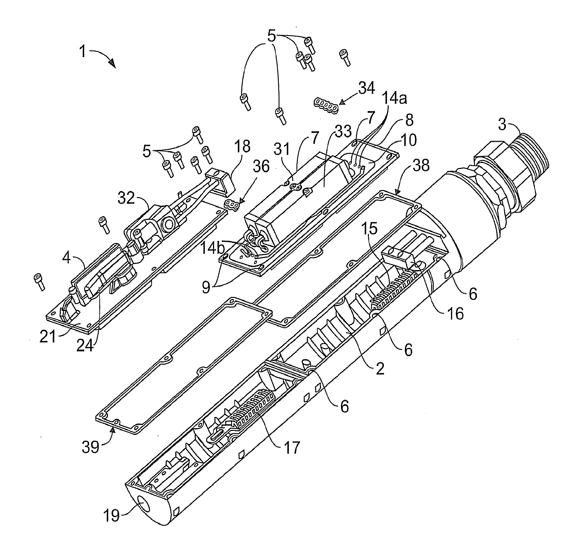
Figure 1 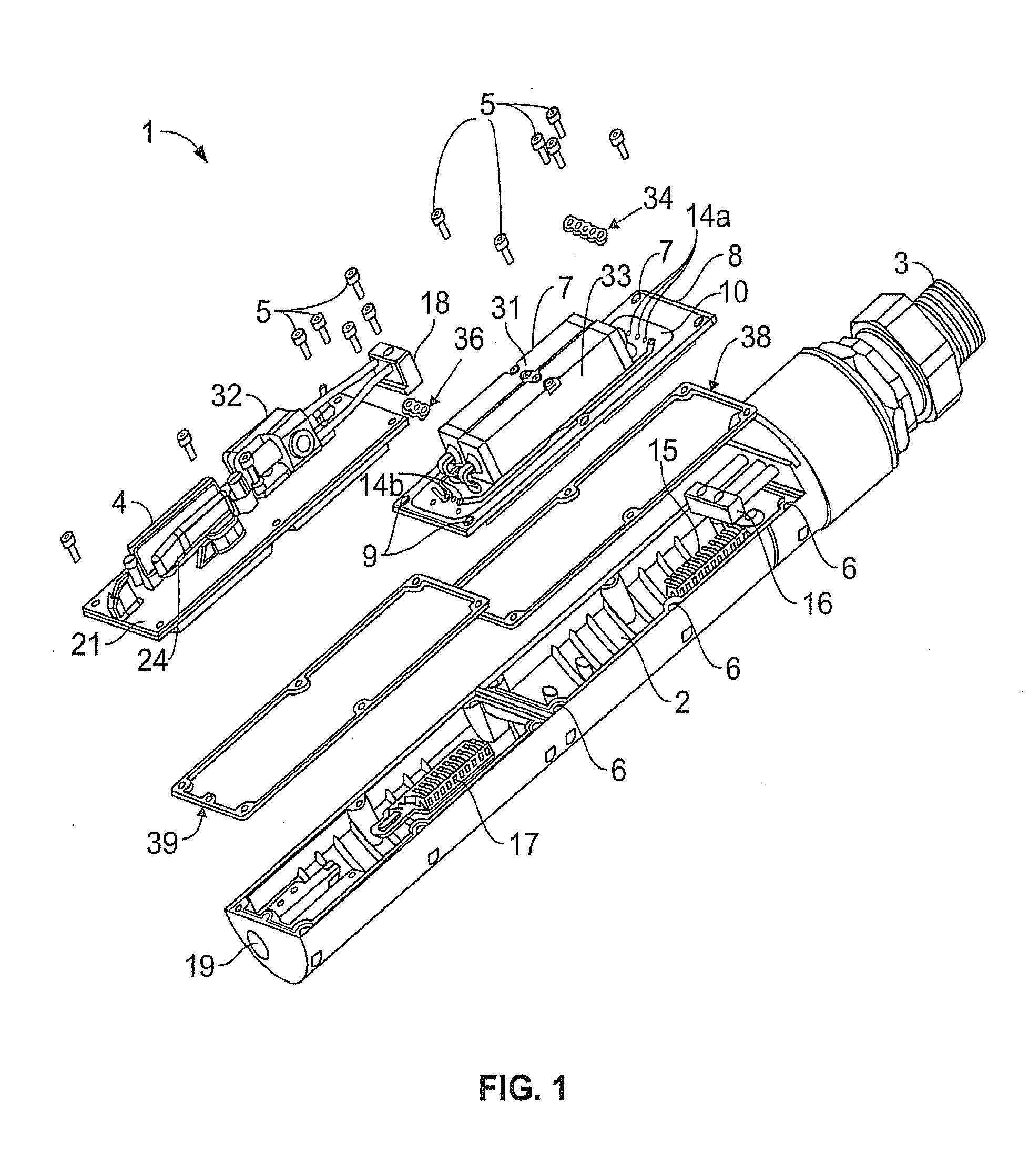
Figure 2 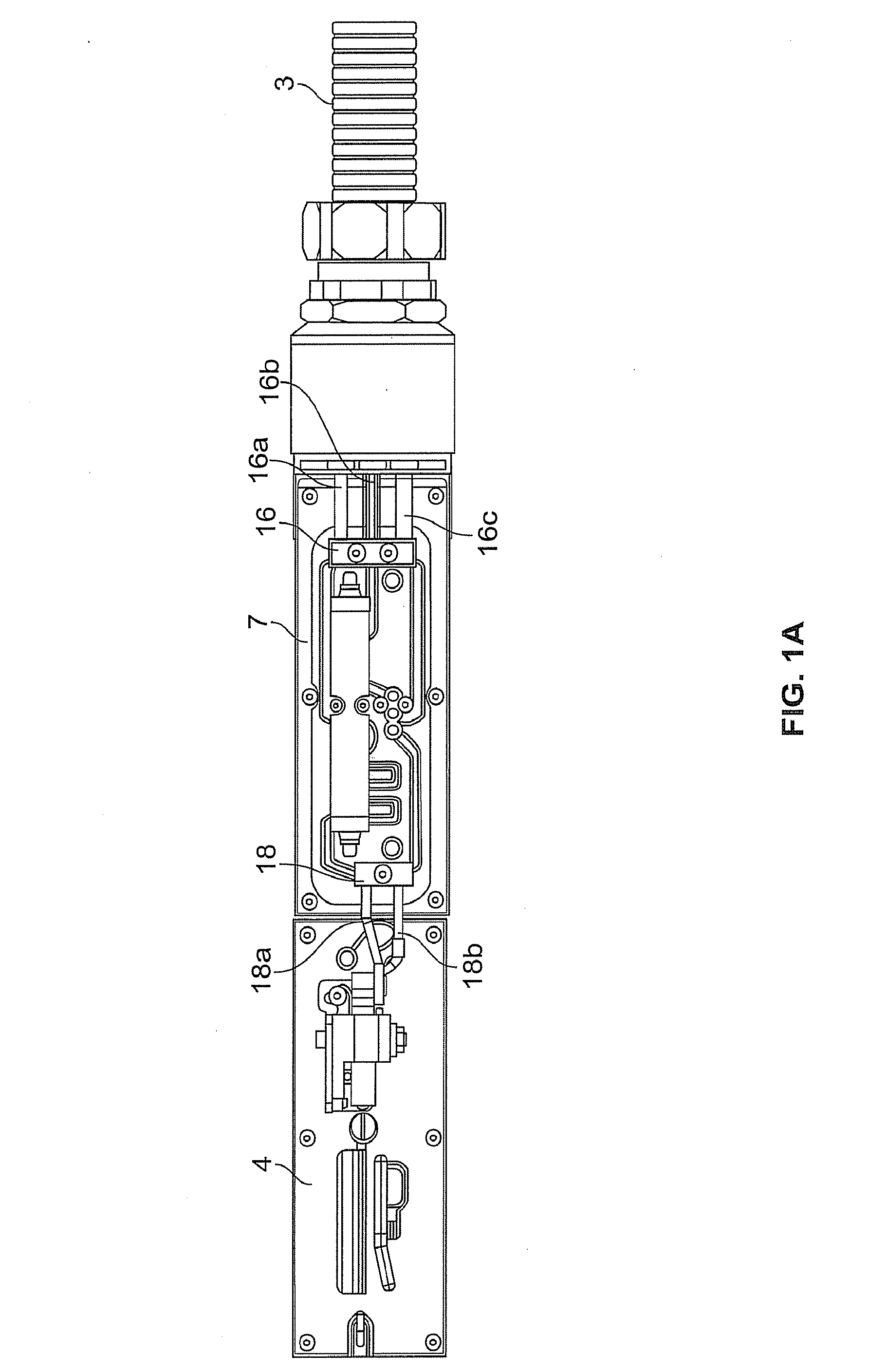
Figure 3
Abstract
Description
[0001] The present invention relates to ink jet printing and more particularly to a print head assembly for an ink jet printer such as a continuous ink jet printer.BACKGROUND
[0002] In ink jet printing systems the print is made up individual droplets of ink generated at a nozzle and propelled towards a substrate. There are two principal systems: drop on demand where ink droplets for printing are generated as and when required; and continuous ink jet printing in which droplets are continuously produced and only selected ones are directed towards the substrate, the others being recirculated to an ink supply.
[0003] Continuous ink jet printers supply pressurised ink to a print head assembly, which has a heater for raising the temperature of the ink to a controlled temperature and a drop generator where a continuous stream of ink emanating from a nozzle is broken up into individual regular drops by an oscillating piezoelectric element. The drops are directed past a charge electrode where the...
Examples
Embodiment Construction
[0045]Referring now to FIG. 1, this shows a print head assembly 1 having a chamber 2 connected to a supply conduit 3 linking the print head assembly 1 to the rest of the printer (not shown). An ink droplet generator module 4 is shown attached to the chamber 2 by bolts 5 mating with tapped holes 6. A seal or gasket 39 may be disposed between ink droplet generator module 4 and chamber 2. The ink droplet generator 4 module (described in further detail below) may include such elements as a piezoelectric element acting as ink droplet generator, a charge electrode, deflector plates, a phase measurement system, a gutter and an exit region 19 where the droplets are printed.
[0046]A heater module 7 has a plate 8 having holes 9 by means of which it may be attached to the chamber 2 using the bolts 5 in the tapped holes 6. A seal or gasket 38 may be disposed between heater module and chamber 2. A shim 10 is welded to the plate 8 forming a heater module manifold with fluid pathways formed between...