
Assembly and method of facilitating the cleaning of an endotracheal tube
a technology of endotracheal tube and cleaning method, which is applied in the direction of cleaning process and apparatus, respirator, other medical devices, etc., can solve the problems of unfavorable extension or protrusion of the distal end of the tubular member, and achieve the effect of efficient and reliable way
Patent Information
- Authority / Receiving Office
- US · United States
- Patent Type
- Applications(United States)
- Current Assignee / Owner
- Publication Date
- 2011-07-28
- Estimated Expiration
- Not applicable · inactive patent
Smart Images
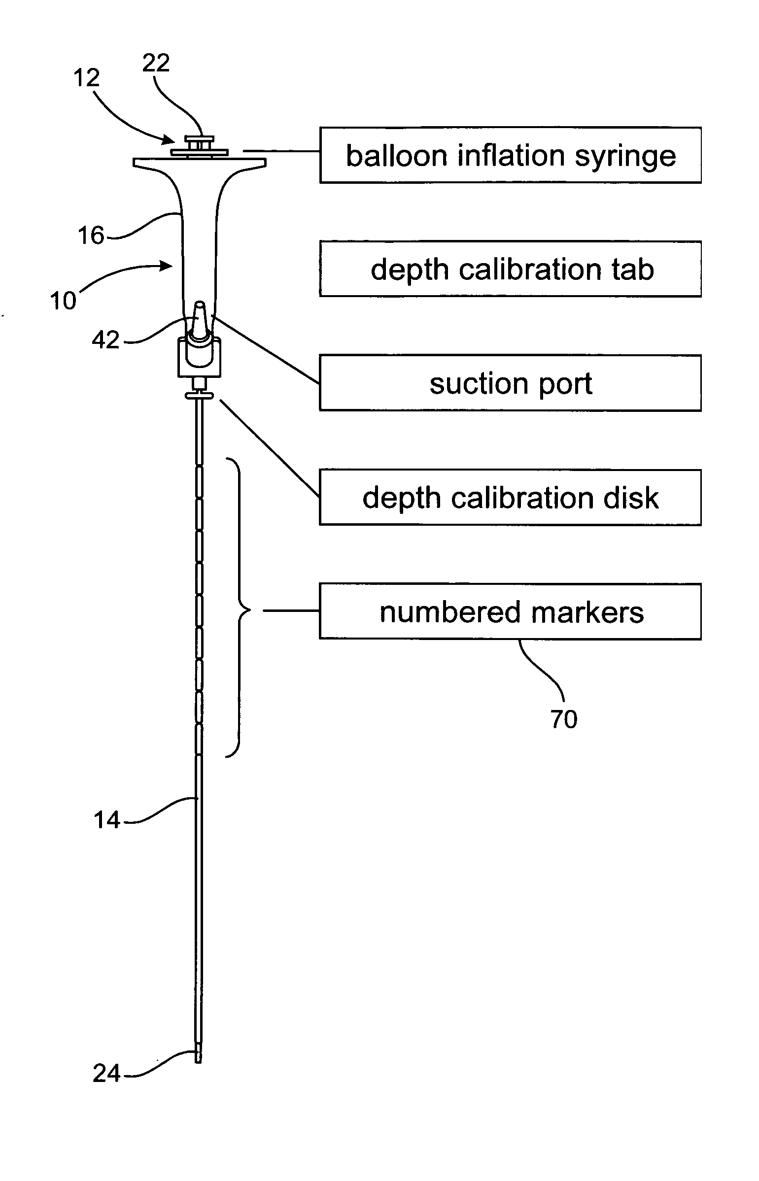
Figure 1 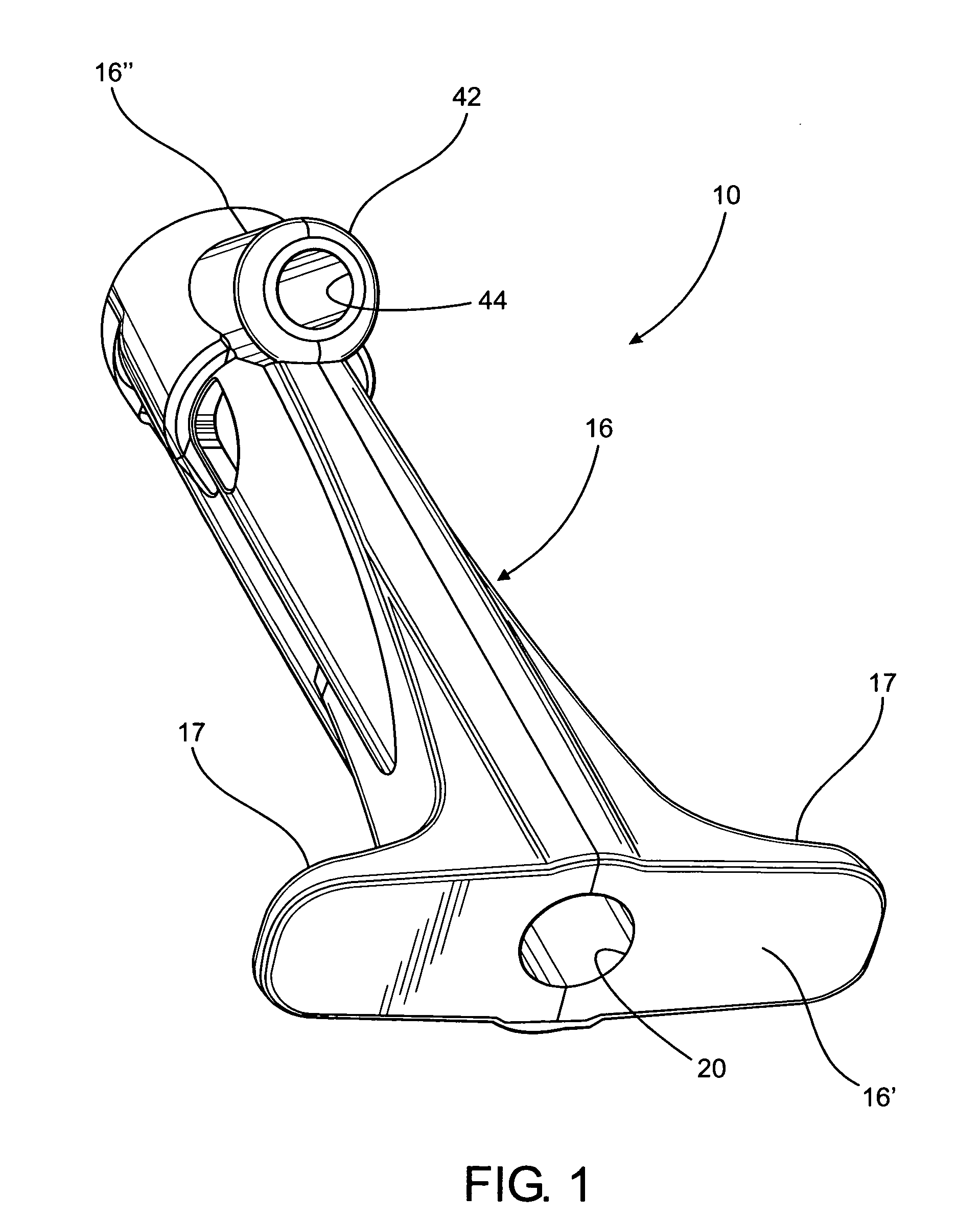
Figure 2 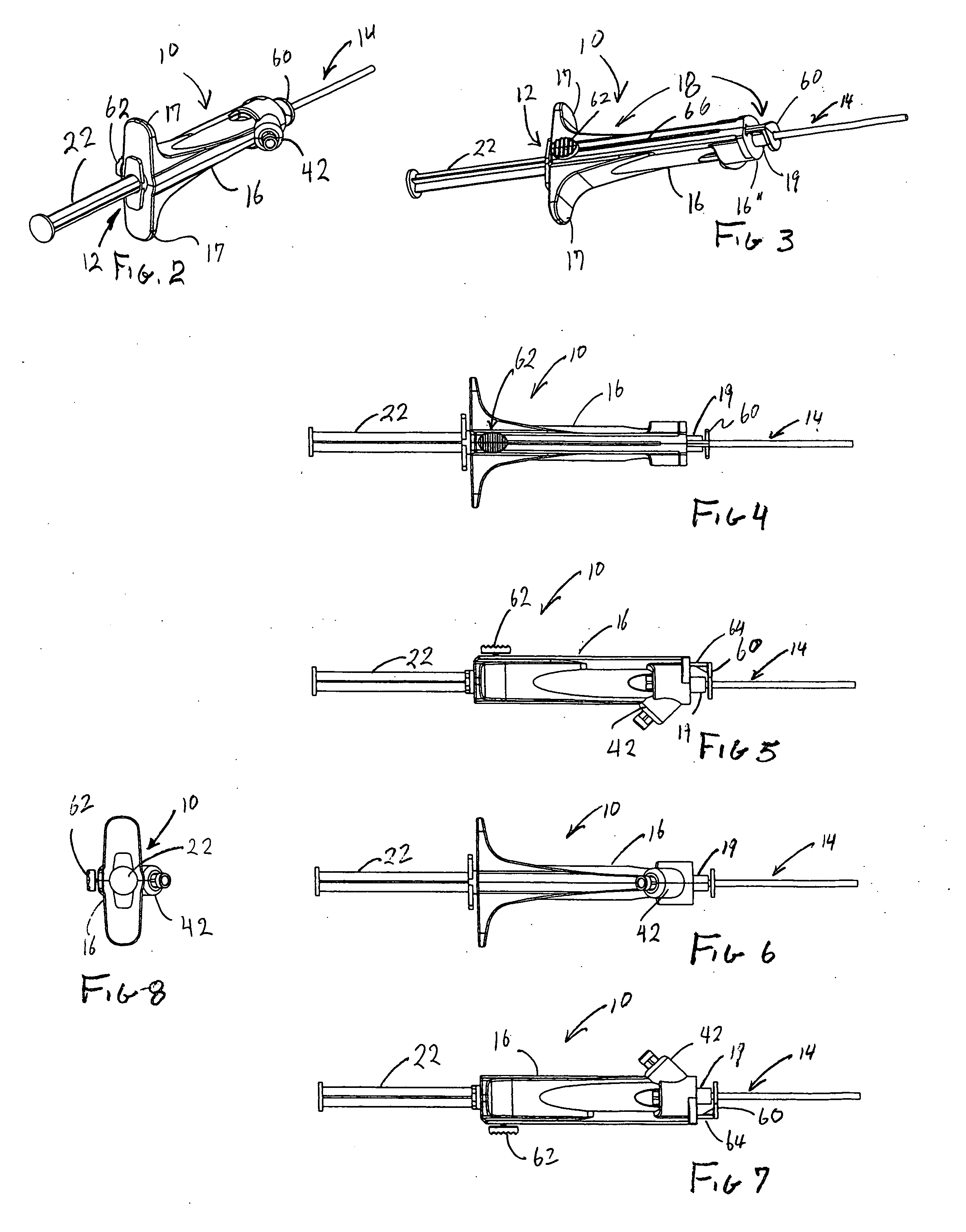
Figure 3
Abstract
Description
BACKGROUND OF THE INVENTION
[0001] 1. Field of the Invention
[0002] This invention is directed to a handle assembly and a method of using it to facilitate the cleaning of an interior of an endotracheal tube. A hand held body comprises a calibration assembly which determines the proper length of a tubular member / catheter to be inserted within the endotracheal tube to efficiently accomplish the cleaning procedure. The calibration assembly is manipulated for selective positioning on and relative to the body in order to determine an appropriate length of the tubular member to be inserted within the endotracheal tube to accomplish the cleaning procedure, while preventing the potentially dangerous extension of the tubular member out of the open internal, distal end of the endotracheal tube.
[0003] 2. Description of the Related Art
[0004] Many patients in a hospital and in particular, patients in an Intensive Care Unit (“ICU”) must be fitted with endotracheal tubes to facilitate their respiration....
Examples
Embodiment Construction
[0041]As shown in the accompanying drawings, the present invention is directed to a handle assembly, generally indicated as 10, which when connected to or assembled with other operative components, facilitates the cleaning of an interior of an endotracheal tube 100, while the endotracheal tube is positioned within a patient. As set forth in greater detail hereinafter, the aforementioned cooperative components with which the handle assembly 10 is assembled and / or connected includes an expansion device generally indicated as 12 and an elongated tubular member or catheter structure 14 represented in an assembled form in FIGS. 2-8, 9A, 9B, 11A, 11B, 12 and 13.
[0042]The handle assembly 10 comprises a body generally indicated as 16 having a generally elongated configuration and being further structured and configured to be held by a hand of a user, as at least partially represented in FIG. 13. As represented the body 16 may be gripped in a manner which facilitates the manipulation of the ...