
Magnetic nail punch and countersink device
a magnetic nail and countersink technology, applied in the field of nail punches, can solve the problems of failure to provide and/or provide devices, complicated parts, etc., and achieve the effect of simple devices
Patent Information
- Authority / Receiving Office
- US · United States
- Current Assignee / Owner
- Publication Date
- 2011-08-25
- Estimated Expiration
- Not applicable · inactive patent
Smart Images
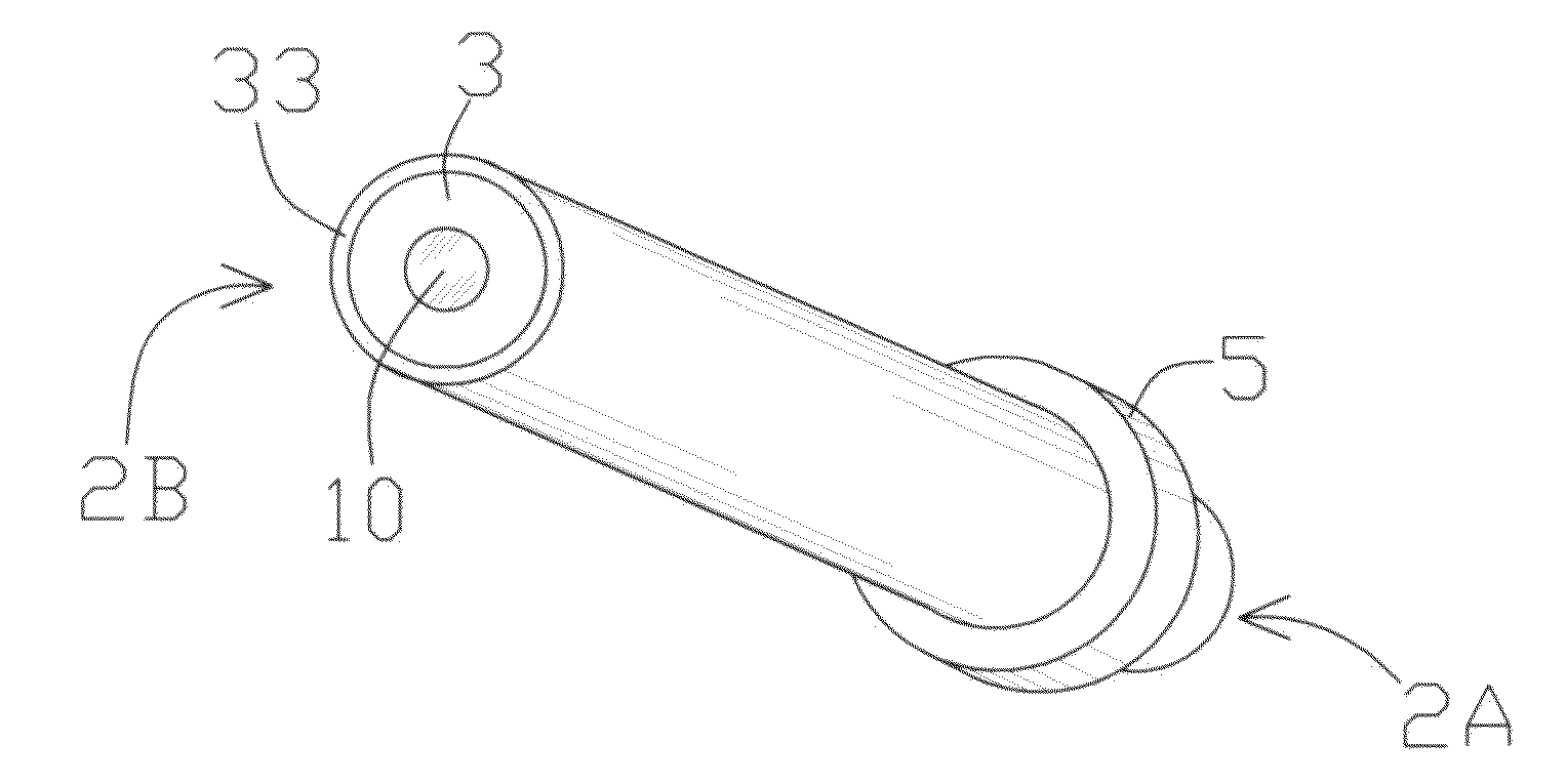
Figure 1 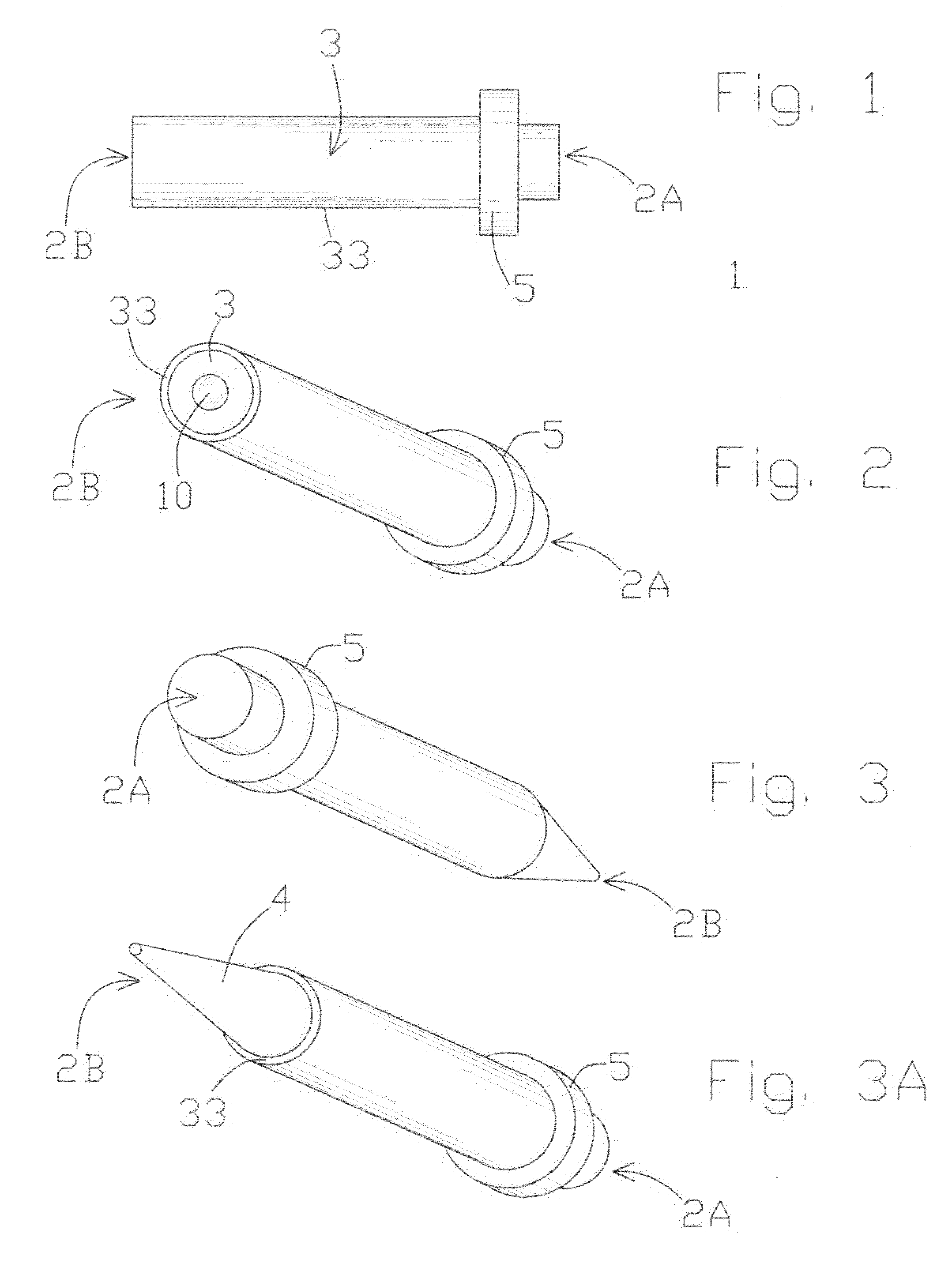
Figure 2
Abstract
Description
[0001] This present relates to U.S. Provisional Patent Application Ser. No. 61 / 338,827 filed on Feb. 23, 2010 and claims priority there from.
[0002] The subject matter of the present invention did not receive federal government research and development funding.TECHNICAL FIELD
[0003] Generally, the present invention relates to a nail punch used in conjunction with a hammer and for assisting a carpenter or other user in seating nails into materials that are located in tight spaces where it is difficult to drive the nails. More specifically, the invention is a magnetic nail punch that includes a lip region that protects a user's fingers as the nails are driven into the materials. A hammer strikes the proximal end of the nail punch to drive a nail arranged on the distal end into a material.BACKGROUND OF THE INVENTION
[0004] There are several types of nail driving devices for assisting one in driving a nail. Some include devices for use in tight spaces or relatively inaccessible places. By way ...
Examples
Embodiment Construction
[0017]The embodiments of the invention and the various features and advantageous details thereof are more fully explained with reference to the non-limiting embodiments and examples that are described and / or illustrated in the accompanying drawings and set forth in the following description. It should be noted that the features illustrated in the drawings are not necessarily drawn to scale, and the features of one embodiment may be employed with the other embodiments as the skilled artisan recognizes, even if not explicitly stated herein. Descriptions of well-known components and techniques may be omitted to avoid obscuring the invention. The examples used herein are intended merely to facilitate an understanding of ways in which the invention may be practiced and to further enable those skilled in the art to practice the invention. Accordingly, the examples and embodiments set forth herein should not be construed as limiting the scope of the invention, which is defined by the appen...