
Battery pack for electric power tool
a battery pack and electric power tool technology, applied in secondary cell servicing/maintenance, batteries, cell components, etc., can solve the problem of not serving to fix the battery cells, achieve the effect of simplifying the molding enhancing the integration of the cell holder, and obtaining elasticity
Patent Information
- Authority / Receiving Office
- US · United States
- Patent Type
- Applications(United States)
- Current Assignee / Owner
- Publication Date
- 2014-10-09
Smart Images
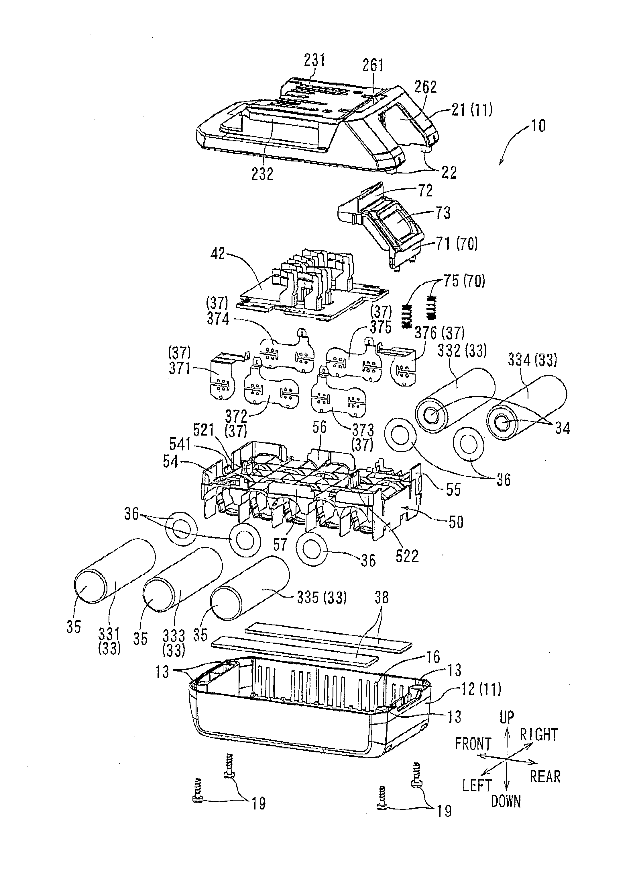
Figure 1 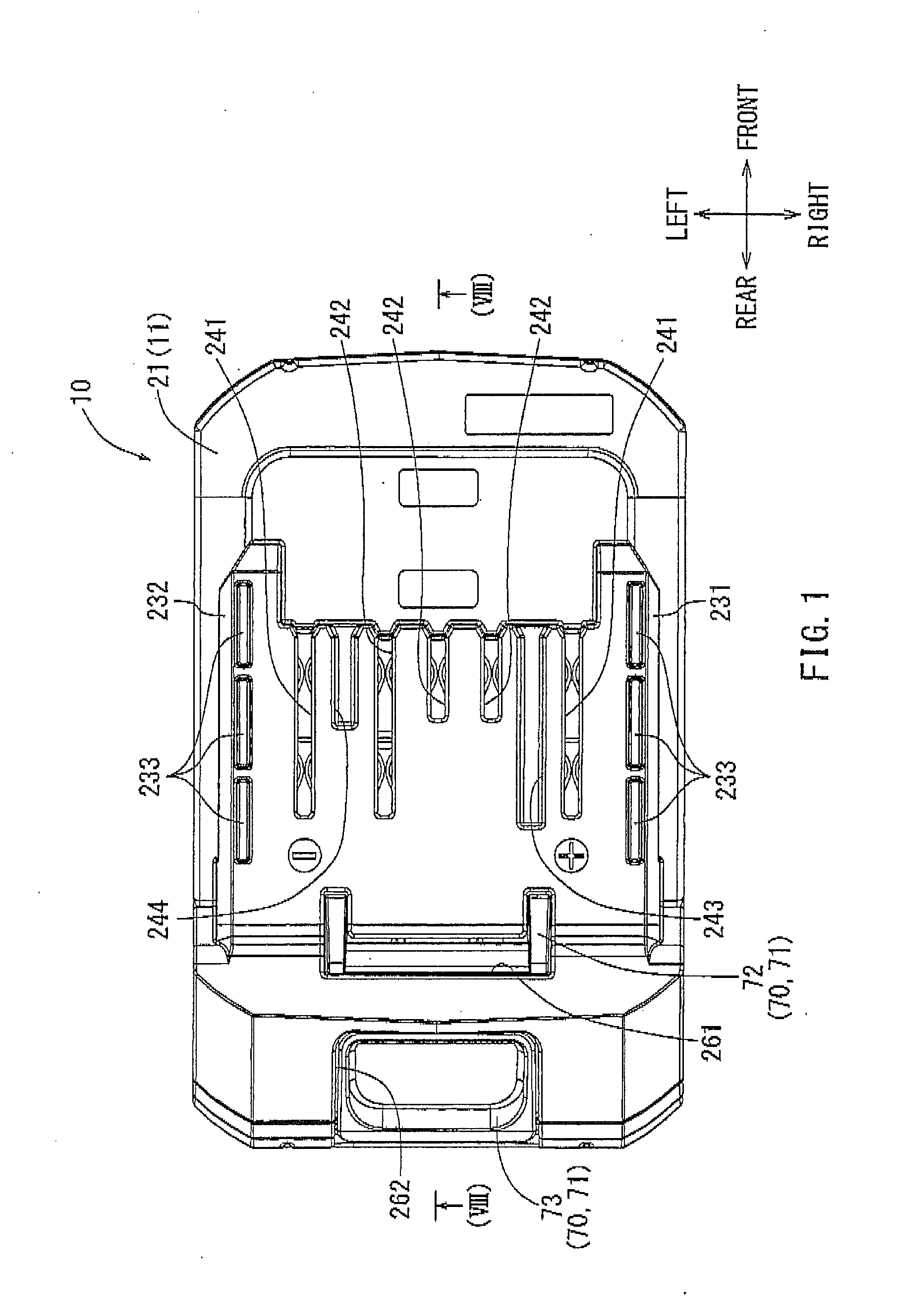
Figure 2 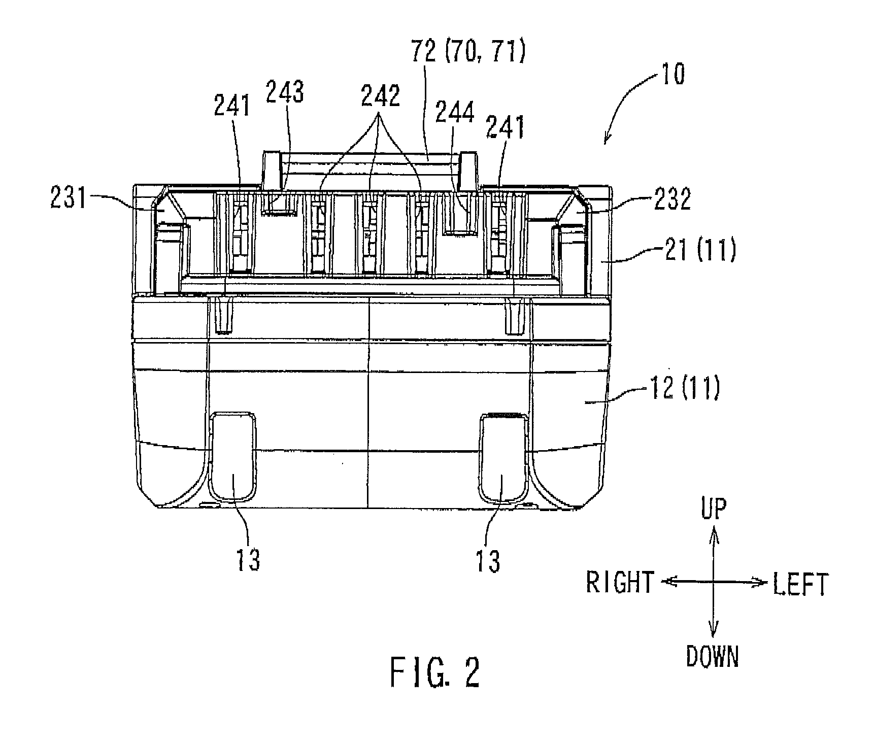
Figure 3
Abstract
Description
[0001] This application claims priority to Japanese patent application serial number 2013-78793, the contents of which are incorporated herein by reference.BACKGROUND OF THE INVENTION
[0002] 1. Field of the Invention
[0003] The present invention relates to a battery pack for an electric power tool that is detachably mounted on a tool body of the electric power tool as a power source for the electric power tool.
[0004] 2. Description of the Related Art
[0005] A battery pack for an electric power tool, which is detachably mounted on a tool body as a power source, has been used in electric power tools. A user can conveniently use an electric power tool when the battery pack for the electric power tool is mounted on the tool body. The battery pack for an electric power tool generally includes a case that serves as a housing as well as forming an outer package, and a battery body that is provided in the case. The case is generally formed by combining an upper and a lower case. Further, the batter...
Examples
first embodiment
[0058]A battery pack for an electric power tool according to a first embodiment of the invention will be described below with reference to FIGS. 1 to 18. Reference numeral 10 shown in FIG. 1 denotes a battery pack that corresponds to a battery pack for an electric power tool according to an embodiment of the invention. The battery pack 10 is a rechargeable battery that is adapted to be detachably mounted via sliding onto tool bodies of various electric power tools typified by, for example, an electric screwdriver. The battery pack 10, which is mounted on a tool body, functions as a power source of an electric power tool. For this purpose, when the amount of the charge of the battery pack 10 is reduced, the battery pack 10 is detached from the tool body and is mounted on a dedicated charger so as to be charged. The battery pack 10, which has been completely charged by the dedicated charger, is mounted on the tool body again as a power source for the electric power tool. Meanwhile, th...
second embodiment
[0095]Next, a battery pack 10A according to a second embodiment of the invention will be described below with reference to FIGS. 19 to 22. As described below in the second and fourth embodiments, battery packs 10A to 10C are created by modifying a part of the structure of the cell holder 50 of the battery pack 10 of the first embodiment. Differences between portions of cell holders 50A to 50C of the battery packs 10A to 10C in the second to fourth embodiments and the above-mentioned cell holder 50 will be described. Portions of the battery packs 10A to 10C according to the second to fourth embodiments, which are the same as portions of the battery pack 10 according to the above-mentioned first embodiment, are denoted in the drawings using the same reference numerals, and the description thereof will be omitted.
[0096]As shown in FIGS. 19 to 22, the cell holder 50A of the second embodiment is different from the cell holder 50 of the first embodiment in terms of the curved shapes of su...
third embodiment
[0099]Next, a battery pack 10B for an electric power tool according to a third embodiment of the invention will be described below with reference to FIGS. 23 to 28.
[0100]As shown in FIGS. 23 to 28, the cell holder 50B of the third embodiment is different from the cell holder 50 of the first embodiment in terms of the arrangement structure of the dimensional difference interposition member of the invention. That is, in the first embodiment, only the front pressing rib 541 is provided as the dimensional difference interposition member at the front side of the cell holder 50. In contrast, dimensional difference interposition members of the third embodiment are formed at portions corresponding to four directions. They are formed on the front side, the rear side, the left side, and the right side of the cell holder 50. That is, the same front pressing rib 541 of the above-mentioned first embodiment is formed at the front wall portion 54 of the cell holder 50B of the third embodiment. Fur...